Hi,
I admire their efforts to achieve a good smps, perhaps the road is still long.
Meanwhile, 4x0.4 = 1.6 (only in mathematics) is not on the wires.
Correct
Does 36KB mean it HAS to be corrupted? I have no problem with it, so can you re-download?This file is corrupted, it shows as only 36kB.
Can you repost?
Took another look at this design and I must still say I like it. What puzzled me though is that there is no output inductor, quite unusual for a forward converter. But it is possible and doable, although it has a few downsides:
- regulation is difficult (not a problem here since there is no voltage regulation loop)
- high peak currents at turn on (not a problem here, since the thermistor at the input will limit the currents on turn on)
These peak currents are only limited by the ESR of the output caps and transformer (both probably quite low), the RDSON of the MOSFETs and the ESL of the transformer, also quite low.
Audia, is it possible to blow the MOSFETs with a short moment of input power missing? Did you (by any chance) measure the current peaks at turn on ? Just curious......
Also, your gate resistors seem quite low, increasing them a little bit might help wiht the noise and voltage peaks...
Attached the schematic pdf again for those whou couldnt download, it worked fine on my computer
Attachments
SMPS HELP
OK
While, as it seems to me you are professional into power electronics.
I would like to know from you:
1- What is the deference between SMPS for Audio and SMPS for LCD TV?
2- What is your suggestions to improve my SMPS above?
3- Can you suggest me a schematic for commercial SMPS unit? that you will not make it bleed.
4- How you can help me with output inductors? Tel me whats missing
I understand your robust experience into SMPS, its clear to me
, Hope to help me out
Turn On current? hmmm I never blew any Mosfet. I know what I am doing
That SMPS is not the END of the world, its a proto, and will improve it
Took another look at this design and I must still say I like it. What puzzled me though is that there is no output inductor, quite unusual for a forward converter. But it is possible and doable, although it has a few downsides:
- regulation is difficult (not a problem here since there is no voltage regulation loop)
- high peak currents at turn on (not a problem here, since the thermistor at the input will limit the currents on turn on)
These peak currents are only limited by the ESR of the output caps and transformer (both probably quite low), the RDSON of the MOSFETs and the ESL of the transformer, also quite low.
Audia, is it possible to blow the MOSFETs with a short moment of input power missing? Did you (by any chance) measure the current peaks at turn on ? Just curious......
Also, your gate resistors seem quite low, increasing them a little bit might help wiht the noise and voltage peaks...
Attached the schematic pdf again for those whou couldnt download, it worked fine on my computer
OK
While, as it seems to me you are professional into power electronics.
I would like to know from you:
1- What is the deference between SMPS for Audio and SMPS for LCD TV?
2- What is your suggestions to improve my SMPS above?
3- Can you suggest me a schematic for commercial SMPS unit? that you will not make it bleed.
4- How you can help me with output inductors? Tel me whats missing
I understand your robust experience into SMPS, its clear to me
, Hope to help me out
Turn On current? hmmm I never blew any Mosfet. I know what I am doing
That SMPS is not the END of the world, its a proto, and will improve it
Hi Audia,
again, your power supply is fine. There is no mistake, and I never used the word.
It just looks to me that you traded output voltage precision ( which would require a feedback loop) for dynamic power delivery. Thats a design choice, not good or bad as such.
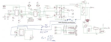
I would only suggest that (due to the reasons on peak current stated earlier) you might want to consider an inrush current protection e.g. with discharging C33 when the current gets too high, like 2x the nominal input current. I have attached a proposal how that could be implemented. You may need to play with the component values a little bit, as I haven'T tested this.
just my two cents...
again, your power supply is fine. There is no mistake, and I never used the word.
It just looks to me that you traded output voltage precision ( which would require a feedback loop) for dynamic power delivery. Thats a design choice, not good or bad as such.
I would only suggest that (due to the reasons on peak current stated earlier) you might want to consider an inrush current protection e.g. with discharging C33 when the current gets too high, like 2x the nominal input current. I have attached a proposal how that could be implemented. You may need to play with the component values a little bit, as I haven'T tested this.
just my two cents...
Attachments
Hi Audia,
again, your power supply is fine. There is no mistake, and I never used the word.
It just looks to me that you traded output voltage precision ( which would require a feedback loop) for dynamic power delivery. Thats a design choice, not good or bad as such.
I would only suggest that (due to the reasons on peak current stated earlier) you might want to consider an inrush current protection e.g. with discharging C33 when the current gets too high, like 2x the nominal input current. I have attached a proposal how that could be implemented. You may need to play with the component values a little bit, as I haven'T tested this.
just my two cents...
I already have current protection circuit witch works perfectly.
Thanks for your idea.
You told me nothing about Output Inductors and how they will improve the overall performance of my SMPS
Thanks
Hi Audia,
sorry here some comments on your questions:
1- What is the deference between SMPS for Audio and SMPS for LCD TV?
Audio is much more a dynamic load than a TV. And, the noise should be low, especially in the audio range. That will usually require a different design, such as yours. For TVs, voltage stability is mandatory since it might impact hte brightness and colours significantly, and the lifetime of the display. Also, they need highest efficiency since the power supply usually is integrated into the flatscreen, and if it were hot it would show up in the image.
2- What is your suggestions to improve my SMPS above?
As per my previous post, nothing much to add except inrush (over-) current protection.
3- Can you suggest me a schematic for commercial SMPS unit? that you will not make it bleed.
Again, your design is fine. "make it bleed" probably refers to blowing MOSFETs, and here I would like to quote wayne colburn from pass labs, who said "your design isnt finished until you can break it and repair at will". So, blowing some parts is part of the fun!
4- How you can help me with output inductors? Tel me whats missing
The output inductors are usually used to store energy and smooth out the rectangular pulses you are sending from the primary side. In your design, the output caps do that job. If the power supply works for you, I would leave it as it is. Any output inductor may reduce peak output current delivery.
What's the switching frequency of this converter?
just my two cents
very nice. May I ask a couple more questions please?
Does the power supply require a minimum load to operate properly?
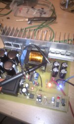
You mentioned for the transformer 11+11:8+8 turns on ETD49, is it gapped, and what inductance values?
interesting way of using the scope probe as a magnetic field sensor! Do you happen to know the website bcarsten.com? There is an appnote that shows how to build your own magnetic field sensor, with some performance data (parts of it repeated in linear tech's appnote AN67). this is nice to find magnetic "hot spots" in your design...
good stuff, I am tempted to build one myself....
Does the power supply require a minimum load to operate properly?
You mentioned for the transformer 11+11:8+8 turns on ETD49, is it gapped, and what inductance values?
interesting way of using the scope probe as a magnetic field sensor! Do you happen to know the website bcarsten.com? There is an appnote that shows how to build your own magnetic field sensor, with some performance data (parts of it repeated in linear tech's appnote AN67). this is nice to find magnetic "hot spots" in your design...
good stuff, I am tempted to build one myself....
very nice. May I ask a couple more questions please?
Does the power supply require a minimum load to operate properly?
You mentioned for the transformer 11+11:8+8 turns on ETD49, is it gapped, and what inductance values?
interesting way of using the scope probe as a magnetic field sensor! Do you happen to know the website bcarsten.com? There is an appnote that shows how to build your own magnetic field sensor, with some performance data (parts of it repeated in linear tech's appnote AN67). this is nice to find magnetic "hot spots" in your design...
good stuff, I am tempted to build one myself....
Thanks for the Link, it looks cool
My SMPS needs no minimum load to operate, why it should?
ETD49 Gapped
Will let you know inductance values
Thanks

- Status
- This old topic is closed. If you want to reopen this topic, contact a moderator using the "Report Post" button.
- Home
- Amplifiers
- Power Supplies
- 1000W SMPS Based on IR2110