I'm trying to get something like this to work. My thought was to get both the needed input stage voltages (about +510 VDC and -35VDC for ccs'ed LTP tail) from one secondary winding by use of zener string shunt regulation and ground/earth offset.
(In this case the other hv secondary has other usage planned for it so thats the reason I went with the voltage doubler circuit and "230V" secondarys)
What do you guys think? What are the problems (there always are it seems...) and how can I improve on this circuit?
(In this case the other hv secondary has other usage planned for it so thats the reason I went with the voltage doubler circuit and "230V" secondarys)
What do you guys think? What are the problems (there always are it seems...) and how can I improve on this circuit?
Attachments
Last edited:
Honestly, I do not like very much the look of this supply, but as long as you have done your homework (current in any of the zeners for any combination of output currents for any mains voltage, etc), it should work as intended.
You are talking about +510 and -35 supplies, but the way it is drawn is a 545V supply with a 35V tap.
This is OK, as you draw the 60mA current from the extremes, but if you really use it as +510 and -35 sources, there might be problems with zener currents.
If you simply need an auxiliary -35V, I think adding a capacitive supply to the 0V side of the main supply would give more independence, see this example:
Attachments
I'm not a fan of long zener strings. Depending on voltages and currents, if one fails (shorted is typical) more tend to fail, then the whole string goes. Also, each zener may have a decent shaped knee, but all strung together the performance may not be that great. OTOH, I used to work for a place that sold high voltage power supplies built that way, and they mostly worked OK.
Elvee, Conrad,thanks very much for your time and efforts to help.
Yes I plan to use voltage from the extremes, driving 2 series coupled long tailed pairs. The gnd offset only makes it possible to loose an input cap really...And as you pointed out Conrad, that long zener string feels like an accident waiting to happen, but thats what that iteration needed to cope with the different current requirements I had planned for that layout (~5-65mA) using 5w zeners. Have already realized that was a bad idea anyway.
So perhaps a capacitive b- supply and some other variant of regulation for the hv b+ would be next for me to investigate. Perhaps something like this to take the load off the zeners: (attachement) but takes the fun/beauty of simplicity away... Well, hope I learn some more as I go along with this.
Attachments
You can retain the shunt regulator, but in a streamlined form.
Here is an example: the MOS cascodes the output of the TL431, and a series resistor R1, bears the brunt of the dissipation.
In series with the drain of M1, the effect on the quality of the regulation is negligible.
Performances will be better than a plain zener, and the reliabilitywill be improved too.
Attachments
After some thinking, here is what I think I will try first.
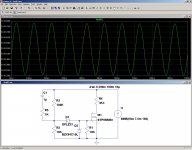
After psu filter, a current source that is shunt regulated at the output. Low ripple according to ltspice, ~300uV, but who knows, perhaps it sucks the life out of music...") (that is with the max designed output ~65mA@~530V, much much lower at more modest output )
(that is with the max designed output ~65mA@~530V, much much lower at more modest output )
What I dont like is that tl431 circuit, too much ic for my taste...but it has good reputation. ?
The irfpg40 shunt mosfet is a tough beast and perhaps severe overkill for the application, but it has high power rating and doesnt cost a fortune.
The ccs set potentiometer could (should) be changed to a 250 or 500 Ohm variant for this use as the resistors for gnd divider, shunt voltage and capacitor equalizer wants about 4mA even without any output load so not much use to be able to set the ccs under 5-6mA perhaps and a lower R pot would increase setting resolution.
After psu filter, a current source that is shunt regulated at the output. Low ripple according to ltspice, ~300uV, but who knows, perhaps it sucks the life out of music...
(that is with the max designed output ~65mA@~530V, much much lower at more modest output ) What I dont like is that tl431 circuit, too much ic for my taste...but it has good reputation. ?
The irfpg40 shunt mosfet is a tough beast and perhaps severe overkill for the application, but it has high power rating and doesnt cost a fortune.
The ccs set potentiometer could (should) be changed to a 250 or 500 Ohm variant for this use as the resistors for gnd divider, shunt voltage and capacitor equalizer wants about 4mA even without any output load so not much use to be able to set the ccs under 5-6mA perhaps and a lower R pot would increase setting resolution.
Attachments
Last edited:
I'm not totally set in using that divider gnd reference scheme, I do think it makes sense to use one psu for the circuits using it. In this case what it does is make it possible to use a solid state ccs at the input stage long tailed pair tail and NOT having a input capacitor.
Another option to the voltage divider would be similar to my initial scetch with zeners but using volage regulator tubes instead, 3x serial VR150 to get +450V to gnd and a VR75 below that to make -75V. Then I could ditch that semi/ic shunt also but I would have a veritable forest of tubes on the chassis...
Also I'm contemplating using a similar scheme for a cathode follower type output tube driver, where you would set the output tube bias by offsetting the whole cf driver circuit/psu with respect to gnd. I think it could be a good idea but I haven't yet simulated what would happen if the driver circuit draws grid current from the output stage (very likely scenario in my application =otl circlotron/parallell single ended)
Perhaps I have done total overkill here, I don't know.
Please comment or advice.
What I dont like is that tl431 circuit, too much ic for my taste...but it has good reputation. ?
OK, designing purely discrete shunt regulators isn't difficult either: here are one or two examples, good, better, ... etc
Attachments
Many thanks Elvee!
In your opinion, what would be the best "bang for the buck" shunt to build, weighing performance/simplicity/setup difficulty/reliability?
Simple is semi-important to me as it will sit in a ptp wired design...don't want all too many pcb's soiling the amps.
I can calculate or simulate almost anything but I don't have an ee degree or pro experience so I haven't yet learned what general semiconductor/ic characteristics that would be sought after to optimize such a design...have a little better knowledge in tubes though...
Difficult to tell: it depends on the application.
You went from one extreme to the other, from a crude zener string to a CCS-fed active shunt.
If you post the schematic of what it is supposed to feed, we will have more relevant information to decide what option is preferable.
You went from one extreme to the other, from a crude zener string to a CCS-fed active shunt.
If you post the schematic of what it is supposed to feed, we will have more relevant information to decide what option is preferable.
Yes, you're right. Part of my problem is that I really don't know what I want besides a "good enough" power supply, how clean it needs to be still alludes me in absolute terms, besides that I know from previous experience that a common unregulated crcrclc supply would be good enough. However, I'm frightened to subject my input stage valves to the extreme unloaded voltage from such a unloaded supply, that would be about 650v or thereabout...could see serious problems with that during startup or in malfunction situations...Thence regulation or overvoltage protection. Also I would like to be able to use the same supply to try out different input stages with net currents from 2mA to 60mA, so instead of swapping series resistors in those cases, an easily adjusted ccs fits the bill very fine I think but then that also has some serious performance benefits. So we arrive at a ccs fed shunt regulated psu even though I don't really need that extreme level of performance, but it's reasonably simple so why not go for it anyway. Should sound good I think (or not sound at all really)
In previous builds I've run about 300v without problems (unloaded volage not sky-high) and the 500v I want to try now is really a way to reduce distortion significantly. I'll post some input section variants soon so you can see what I'm up to.
In previous builds I've run about 300v without problems (unloaded volage not sky-high) and the 500v I want to try now is really a way to reduce distortion significantly. I'll post some input section variants soon so you can see what I'm up to.
Very true Andrew,
Simple things like that is what I have a problem finding myself...My relative lack of experience in this field of engineering shows...
Had thought about using thermistors instead of resistors and that could accomplish the same thing one would think but its hard to find ones with large enough cold resistance together with current (power) rating unless one uses a bunch of them in series or parallell =(bad idea current hogging)
Hi, Allen Wright (from Vacuumstate fame) used a LM317 cascoded with a high voltage MOSFET to achieve a simple but effective current source, not using exotic components. you might want to give it a try.....
also, how about a cap multiplier with a TVS at the base ( these devices really are just high power zener diodes)? that should give you reasonable regulation. and if you add a RC lowpass after the TVS, before connecting to the base, you might achieve low noise as well....
just my two cents
also, how about a cap multiplier with a TVS at the base ( these devices really are just high power zener diodes)? that should give you reasonable regulation. and if you add a RC lowpass after the TVS, before connecting to the base, you might achieve low noise as well....
just my two cents
The voltage across your 1N4007 rectifiers is 2.83 times the transformers secondary rating minimum. Allow 10% for high line and 20% for "transformer" regulation. In addition you should allow at least a 10 to 20 % additional safety factor as at these power levels you will have a decent small explosion.
So you will blow up your rectifiers and depending on fusing the filter capacitors also.
So you will blow up your rectifiers and depending on fusing the filter capacitors also.
Seems like a simple voltage limiter is good enough for you.Yes, you're right. Part of my problem is that I really don't know what I want besides a "good enough" power supply, how clean it needs to be still alludes me in absolute terms, besides that I know from previous experience that a common unregulated crcrclc supply would be good enough. However, I'm frightened to subject my input stage valves to the extreme unloaded voltage from such a unloaded supply, that would be about 650v or thereabout...could see serious problems with that during startup or in malfunction situations...Thence regulation or overvoltage protection. Also I would like to be able to use the same supply to try out different input stages with net currents from 2mA to 60mA, so instead of swapping series resistors in those cases, an easily adjusted ccs fits the bill very fine I think but then that also has some serious performance benefits. So we arrive at a ccs fed shunt regulated psu even though I don't really need that extreme level of performance, but it's reasonably simple so why not go for it anyway. Should sound good I think (or not sound at all really)
In previous builds I've run about 300v without problems (unloaded volage not sky-high) and the 500v I want to try now is really a way to reduce distortion significantly. I'll post some input section variants soon so you can see what I'm up to.
In this case, you first choice, the zener string seems almost optimal, except it is crude, clumsy and part intensive.
An equivalent is an amplified zener, see below.
It is simple, rugged, unsophisticated but reliable.
I don't see exactly what you mean: each diode will see 640V prv.The voltage across your 1N4007 rectifiers is 2.83 times the transformers secondary rating minimum.
Add a 50% margin, this becomes 960V. Not exactly unsafe.
Attachments
I don't see exactly what you mean: each diode will see 640V prv.
Add a 50% margin, this becomes 960V. Not exactly unsafe.
What do you take the unloaded secondary voltage as being?
- Status
- This old topic is closed. If you want to reopen this topic, contact a moderator using the "Report Post" button.
- Home
- Amplifiers
- Power Supplies
- Zeners for shunt regulation and ground offset