Is it possible common ground not equal to zero volt? let's say more(+) or less(-) than zero volt.
Does it cause any problem?
Hello,
Just don’t hold common in one hand and earth in the other.
You can reference common to any voltage you want just do it on purpose not by accident.
DT
All just for fun!
So you're saying you've got a power supply with +12V and -12V outputs, and the actual voltages are +12.1 and -11.9. Ground is still 0V and these voltages are still measured with respect to ground. It does not matter if one voltage is a little more than the other. The average of these two voltages may not be exactly 0V, but that's not important. This does not cause a problem.
Now, I finally understand the original question.
You assumed the common voltage was Zero Volts and attached your Black Voltmeter probe to that point.
You measured +12.1Vdc to one line out and measured -11.9Vdc to the other line out.
You have three points (ends/lines out) which relative to each other are +12.1, 0, -11.9
This is exactly the same as 0, -12.1, -24 and is also exactly the same as +24, +11.9, 0
It all depends ONLY on where you decide to call Zero Volts.
You could have a second dual polarity supply giving +80, +65, 0Vdc
You can now connect these two isolated PSU to a Chassis tapping.
Let's assume that the Chassis Tapping is Zero Volts.
Connect the +80 of the +80, +65, 0 to the chassis. You now have 0, -15Vdc, -80Vdc from the second PSU.
Now attach your original +12.1, 0, -11.9Vdc PSU. Let's connect the -11.9V line of that to the -15Vdc tapping.
You end up with 0V at the chassis connected tapping. You still have -15Vdc and -80Vdc. The new connection to the -15Vdc tapping is still -15Vdc relative to chassis. The other two tappings become (-15V) + (+12.1V) = -2.9V and (-15V) + (-11.9V) = -26.9V.
The 5 PSU tappings are 0, -2.9, -15, -26.9, -80Vdc.
Attach your black Voltmeter Probe to chassis and measure the voltage to each of the tappings.
Note there are two wires/lines out connected to the 15V tapping.
That makes a total of 6 PSU tappings from your two dual polarity supplies.
Last edited:
Voltage is always expressed in terms of voltage difference between two points, even if one of the points is not named (or even thought about). So +0.2V means +0.2V higher than what?
Take an isolated circuit which works perfectly. Disconnect its ground reference from 0V and attach it to +5V. The circuit continues to work perfectly. Internally, nothing has changed.
Take an isolated circuit which works perfectly. Disconnect its ground reference from 0V and attach it to +5V. The circuit continues to work perfectly. Internally, nothing has changed.
Going to rebuild the psu, can I connect it in this way?
[url=http://www.diyaudio.com/forums/gallery/showphoto.php/photo/6552]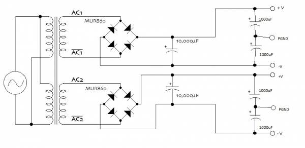
[/URL]
[url=http://www.diyaudio.com/forums/gallery/showphoto.php/photo/6552]
[/URL]
No.
What is the purpose of this power supply? The caps need some DC voltage reference, like a resistor voltage divider or active device. A floating GND is a viable option for light loads but will not work well with low inpedance circuits such as power amplifer output stages. AC1 and AC2 should be perfectly equal, as in bifiler winding, in order to paralell them.
What is the purpose of this power supply? The caps need some DC voltage reference, like a resistor voltage divider or active device. A floating GND is a viable option for light loads but will not work well with low inpedance circuits such as power amplifer output stages. AC1 and AC2 should be perfectly equal, as in bifiler winding, in order to paralell them.
Last edited:
So you're saying you've got a power supply with +12V and -12V outputs, and the actual voltages are +12.1 and -11.9. Ground is still 0V and these voltages are still measured with respect to ground. It does not matter if one voltage is a little more than the other. The average of these two voltages may not be exactly 0V, but that's not important. This does not cause a problem.
No no. I mean I have dual secondary. A secondary and B secondary.
A secondary -neg out -11.9v and B secondary +pos out 12.1v.
If I parallel them(single bridge rectifier), then I will get +0.2v at the ground?
If I parallel them after dual bridge rectifier(imperfect diode 0.6-0.8v drop), then I will get more or less than 0.2v at ground?
Do this cause high offset to the input/output of amp with reference to the non-zero volt ground?
No.
What is the purpose of this power supply? The caps need some DC voltage reference, like a resistor voltage divider or active device. A floating GND is a viable option for light loads but will not work well with low inpedance circuits such as power amplifer output stages. AC1 and AC2 should be perfectly equal, as in bifiler winding, in order to paralell them.
How to get near zero volt ground? Replace transformer?
Earth the ground? How if lightning struck?
Last edited:
Start again...
Firstly ground or a zero point is just some arbitrary reference point that you measure and refer all your signals and voltages too.
If the two secondary voltages are a little unequal then all that happens is that the DC rails are slightly unequal too. That is of no concern what so ever, its not a problem.
The zero line in this PSU can be safely earthed or grounded.
Lightning strike... is a subject on its own.
If a direct hit happens then nothing will make any difference. If a strike happens nearby and gets into the mains supply then anything can happen. I have worked on many electronic items damaged in this way and there is no pattern as to what may or may not fail. Sometimes the wiring in a house is totally destroyed, yet the equipment survives, sometimes every fuse is blown apart yet the equipment still works, other times there is no sign of damage yet many many semiconductors have failed. I have seen and repaired switch mode PSU's with vapourised print, yet they have suffered no component damage.
Attachments
If the two secondaries are not identical, as you seem to be saying, then you cannot parallel them either before or after the bridge rectifiers.
If you place them in series, using two separate rectifier/capacitor arrangements, then you will get a bipolar supply which happens to be slightly unbalanced. No problem. Just ground the point whre they join.
If you place them in series, and use one bridge rectifier, then you get twice the voltage and the 0.2V difference is irrelevant as you are not using the join. If you try to use the join then it will have 0.2V of hum.
Your question, and the circuit in post #7, makes me concerned that you do not understand power supplies sufficiently well to build one safely.
If the two secondaries are not identical, as you seem to be saying, then you cannot parallel them either before or after the bridge rectifiers.
Your question, and the circuit in post #7, makes me concerned that you do not understand power supplies sufficiently well to build one safely.
So it is possible that two secondaries are not identical.
Sorry, my mistake. I want to connect them into series not parallel.
The post#7 I found from google, but without the 10,000uF.
If you place them in series, using two separate rectifier/capacitor arrangements, then you will get a bipolar supply which happens to be slightly unbalanced. No problem. Just ground the point whre they join.
If you place them in series, and use one bridge rectifier, then you get twice the voltage and the 0.2V difference is irrelevant as you are not using the join. If you try to use the join then it will have 0.2V of hum.
If I need the ground point, so it is better to use dual bridge?
No no. I mean I have dual secondary. A secondary and B secondary.
A secondary -neg out -11.9v and B secondary +pos out 12.1v.
If I parallel them(single bridge rectifier), then I will get +0.2v at the ground?
If I parallel them after dual bridge rectifier(imperfect diode 0.6-0.8v drop), then I will get more or less than 0.2v at ground?
Do this cause high offset to the input/output of amp with reference to the non-zero volt ground?
How to get near zero volt ground? Replace transformer?
Earth the ground? How if lightning struck?
You worry needlessly about the "0.2V". Ground is ground. If you decide ground is zero volts, that's what it is. Now you have two power supplies one with +12.1 with respect to ground, the other with -11.9 with respect to ground. This is fully normal, it is very rare that they would be the same - the windings can be just a bit different and you have different voltages. Rebuilding the power supply will give you other differences but most likely not zero.
Your amp will work perfectly normal with these slight differences. The offset is not determined by this but by some issues inside the amp.
jan didden
Yes. I got it. I misunderstood few things about the transformer.
I thought the output of dual secondaries are -12v to 12v and -12v to 12v.
So unbalanced winding between two secondaries will give -12.1v to 12.1v and -11.9v to 11.9v.
I measured from one end to the series connection 12.1v-0-11.9v.
The truth is
dual secondaries with four wires. 0-12v and 0-12v. 0 and 12 is the return path(Neutral) and Live respectively?
Mine 0-12.1v and 0-11.9v. when series connection as ground point, any voltage below it will be negative?
12.1v-0 in series with 11.9v-0 = +12.1v and -11.9v
11.9v-0 in series with 12.1v-0 = +11.9v and -12.1v
Am I correct?
I don't follow you, you need to attach a diagram for me to get what you mean, sorry.
If you have dual secondaries and you want one + and one - voltage, just put them in series, ground the center and use two half-bridges to make the + and - voltage. That's all there is to it. Unless I misunderstand what you need.
jan didden
- Status
- This old topic is closed. If you want to reopen this topic, contact a moderator using the "Report Post" button.
- Home
- Amplifiers
- Power Supplies
- what if common ground not zero volt