My primary intention was to build a 2 amp switch mode Constant Current Source with low power dissipation.
I first tried a self-oscillating approach as published here:
http://www.diyaudio.com/forums/solid-state/144726-switching-current-source-class.html
The way it works is basically that
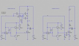
- the current is sensed by means of the 1 ohm resistor
- translated into a voltage by the differential amplifier
- compared to a reference voltage
- the mosfet turns on when below the reference
- and turns off when above the reference.
This is the diagram on the left side. (Note: I am using 1 Ohm and 10 kOhm resistors just for demonstration purposes. Other values may be more efficient.)
It worked well. Despite varying the load resistor between 1 Ohm and 10 Ohms, the current stays fairly constant at 2 amps.
The effective impedance of the CCS was measured to be around 2 kOhm.
Next I wanted to simplify the design, eliminating the differential amplifier by moving the 1 ohm sense resistor to the bottom
i.e. into the source of the mosfet.
This is the diagram on the right side. (Note: it resembles the classic analog 2-transistor CCS except for it is self-oscillating).
My thinking was, that when I controlled the peak current through the inductor to be 2 amps, corresponding to a drop of 2 volts on the 1 ohm sense resistor, this would also control the current through the load.
I was wrong !
When I vary the load resistor between 1 Ohm and 10 Ohms, the current varies also:
1.0 ohm load --> 25 volts / 5 amps
2.5 ohms load --> 20 volts / 4 amps
5.0 ohms load --> 15 volts / 3 amps
It seems that I built a switched mode Constant Resistor of 5 ohms, albeit with a power dissipation of just 1/10 that of a
conventional resistor !!!
- Nice ... maybe this could be useful elsewhere ...
- But why is it not a CCS ?
- Why is the current through the load higher than 2 amps although the comparator should turn off whenever the current through
the sense resistor reaches 2 amps - thereby limiting the peak current in the inductor and hence the load ?
My first suspect was the delay caused by the R/C filter, but modifying the filter doesn't change anything - except the frequency of the oscillation.
I first tried a self-oscillating approach as published here:
http://www.diyaudio.com/forums/solid-state/144726-switching-current-source-class.html
The way it works is basically that
- the current is sensed by means of the 1 ohm resistor
- translated into a voltage by the differential amplifier
- compared to a reference voltage
- the mosfet turns on when below the reference
- and turns off when above the reference.
This is the diagram on the left side. (Note: I am using 1 Ohm and 10 kOhm resistors just for demonstration purposes. Other values may be more efficient.)
It worked well. Despite varying the load resistor between 1 Ohm and 10 Ohms, the current stays fairly constant at 2 amps.
The effective impedance of the CCS was measured to be around 2 kOhm.
Next I wanted to simplify the design, eliminating the differential amplifier by moving the 1 ohm sense resistor to the bottom
i.e. into the source of the mosfet.
This is the diagram on the right side. (Note: it resembles the classic analog 2-transistor CCS except for it is self-oscillating).
My thinking was, that when I controlled the peak current through the inductor to be 2 amps, corresponding to a drop of 2 volts on the 1 ohm sense resistor, this would also control the current through the load.
I was wrong !
When I vary the load resistor between 1 Ohm and 10 Ohms, the current varies also:
1.0 ohm load --> 25 volts / 5 amps
2.5 ohms load --> 20 volts / 4 amps
5.0 ohms load --> 15 volts / 3 amps
It seems that I built a switched mode Constant Resistor of 5 ohms, albeit with a power dissipation of just 1/10 that of a
conventional resistor !!!
- Nice ... maybe this could be useful elsewhere ...
- But why is it not a CCS ?
- Why is the current through the load higher than 2 amps although the comparator should turn off whenever the current through
the sense resistor reaches 2 amps - thereby limiting the peak current in the inductor and hence the load ?
My first suspect was the delay caused by the R/C filter, but modifying the filter doesn't change anything - except the frequency of the oscillation.
Attachments
There is no hysteresis in your systems, which means there will be a fast oscillation around the average value of the set current
In the first case, your current sense resistor senses both the charge and discharge current in the inductor, and the average is correct.
In the second case, it doesnt take into account the charge current during the ON time of the switch.
Note that even with a proper hysteresis, I find this control strategy rather poor: it only works because there is a fixed ratio between the peak and average current.
The regulator should regulate the average current directly (perhaps driving an inner loop based on a current mode switch).
Thanks for your reply.
I actually had a 1 meg positive feedback across the comparator, forgot to put it into the drawing.
Doesn't help the control problem though, just lowers the oscillation frequency.
I was aware of it not measuring the "discharge" current when the switch is off. Had hoped that controlling the "charge" current would also control the "discharge" to some extent. After all the relatively large inductor should keep the same current flowing through the diode and hence the load when the switch is off. Or at least almost the same - since the frequency is high around 500 kHz. So it works in the left circuit. What I didn't expect at all is the constant R effect of the other circuit and for which I have no explanation so far at all.
- Status
- This old topic is closed. If you want to reopen this topic, contact a moderator using the "Report Post" button.