Hi,
I was wondering, what would be the possible problems with this design?
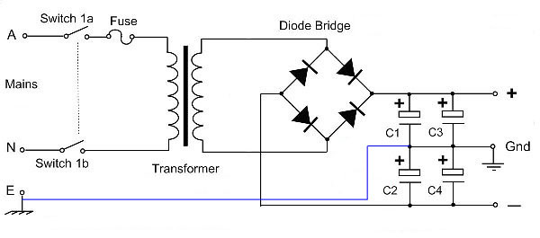
My transformer only has a single secondary winding of 42V. I'm intending to connect it to a filter board, that has AC-GND-AC on the input side. I tested it without connecting the filterboard GND to EARTH (blue line), it gave a split voltage of +/-30V on the filterboard output.
It should power two LM3886 amplifier boards as the end result.
I was wondering, what would be the possible problems with this design?
My transformer only has a single secondary winding of 42V. I'm intending to connect it to a filter board, that has AC-GND-AC on the input side. I tested it without connecting the filterboard GND to EARTH (blue line), it gave a split voltage of +/-30V on the filterboard output.
It should power two LM3886 amplifier boards as the end result.
Thanks for the reply!
I'm afraid it raises even some more questions.
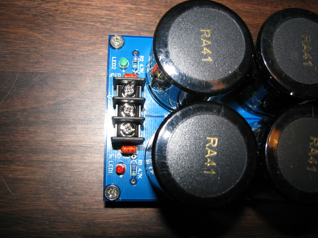
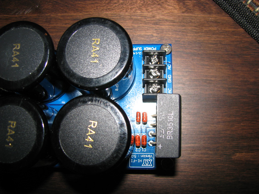
The filter section is actually a bit more advanced, than on the schematic. It is one of those kits that has a multilayer board and comes without a proper shematic (only layout picture). There are two resistors on it, but it's hard to tell if they are for stabilization or for leds (or both?). It came together with the LM3886 boards, so there is a chance it will work for them, but i'm not sure it will work with a single secondary (no center tap) tranformer. See below pictures!
I could be getting it the wrong way, but I was thinking that since the two LM3886 boards (each with one IC) should be running in phase, they could never draw the same current from + and - at the same time. As audio is AC it should be on + or - side, not both at the same time.
Would a center tapped or dual secondary transformer be way better for the application, why so?
I'm afraid it raises even some more questions.
The filter section is actually a bit more advanced, than on the schematic. It is one of those kits that has a multilayer board and comes without a proper shematic (only layout picture). There are two resistors on it, but it's hard to tell if they are for stabilization or for leds (or both?). It came together with the LM3886 boards, so there is a chance it will work for them, but i'm not sure it will work with a single secondary (no center tap) tranformer. See below pictures!
I could be getting it the wrong way, but I was thinking that since the two LM3886 boards (each with one IC) should be running in phase, they could never draw the same current from + and - at the same time. As audio is AC it should be on + or - side, not both at the same time.
Would a center tapped or dual secondary transformer be way better for the application, why so?
")
if you must have a dual polarity supply then you can use half wave rectifying for the two polarities.
Ripple will be roughly doubled.
Almost certainly need to fit rCLC filtering to get decent DC from the supply.
Cheaper to buy a dual or centre tapped secondary.
Consider what the rail voltages would be if you did that with a transformer having a 42 VAC secondary... around +/- 60 VDC. That's far too high for any chip amp I have ever seen.
Thanks for the reply!
I'm afraid it raises even some more questions.
The filter section is actually a bit more advanced, than on the schematic. It is one of those kits that has a multilayer board and comes without a proper shematic (only layout picture). There are two resistors on it, but it's hard to tell if they are for stabilization or for leds (or both?). It came together with the LM3886 boards, so there is a chance it will work for them, but i'm not sure it will work with a single secondary (no center tap) tranformer. See below pictures!
I could be getting it the wrong way, but I was thinking that since the two LM3886 boards (each with one IC) should be running in phase, they could never draw the same current from + and - at the same time. As audio is AC it should be on + or - side, not both at the same time.
Would a center tapped or dual secondary transformer be way better for the application, why so?
A single supply is perfect for amps driving a bridged load, since no current needs to flow back into the ground (it goes rail to rail). You might want to look into going bridged, but you need to carefully consider the impedance of the speakers, rail voltages, etc.
You can also do what you had proposed in the first place. You will need a couple of large (at least 10 watt) resistors to use as ballast resistors. I would guess that your rails will come out to about +/- 28 to 30 VDC, so using a 100 ohm 10 W resistor from each rail to ground would probably work (note that they will get very hot). You will also need to make sure that the amps are AC coupled; this is very important in order to avoid loading one rail more than the other.
You are right about each amp only drawing from one rail or the other at any given instant. This is true. If you realise that bass is where >90% of the power is used, and bass is always in phase between channels, then you will also realize that both amps will tend to draw from the same rail at any given time. Now, you can mitigate the effects of this. Make one side inverting (preferably by inverting the signal then feeding to the amp rather than changing the amp configuration to inverting) so that it draws from the opposite rail as the other amp. Wire that channel's speaker terminals backwards (red: ground, and black: hot). And don't forget that you did this so that you don't assume that the black terminal is the ground one, though you should NEVER assume that anyway. This comes with a bonus feature: you can easily bridge the amp by wiring a speaker of appropriate impedance between the two hot terminals and not using the ground terminals.
Last edited:
Run it single rail with an output capacitor? It's reasonably easy to define a nice stable centre point for the input reference; it's just the speaker current that's upsetting things.
Not elegant, perhaps, but once upon a time nearly all transistor amps were wired like that.
Not elegant, perhaps, but once upon a time nearly all transistor amps were wired like that.
Hi tuhkam,
Quad had a power supply with a virtual ground. You need a couple of transisitors and 4 resistors in parallel with the caps.
http://quadrevisionspot.blogspot.com/2009/12/quad-306-monoblock-virtual-earth.html
regards
Quad had a power supply with a virtual ground. You need a couple of transisitors and 4 resistors in parallel with the caps.
http://quadrevisionspot.blogspot.com/2009/12/quad-306-monoblock-virtual-earth.html
regards
See the comments in this thread:
http://www.diyaudio.com/forums/parts/96815-fake-split-psu.html
http://www.diyaudio.com/forums/parts/96815-fake-split-psu.html
Hi ,I had used this config from my single tap trafo to power up my discrete amp without any transistors just bleeder resistors.I only put 2 15,000 uf filter caps. I just dont know the consequencies of this but luckily until now my amp is operational and does not encounter any breakdown since it was made 3 years ago.
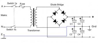
I have another trafo 24vac @ 40 amperes from power supplies and I plan to use it again with the attached rectification and add up capacitances for my circlophone....is there any danger on this? ground is on chassis only since we only have 220Vac -0 line.So line ground or earth is not connected.
I have another trafo 24vac @ 40 amperes from power supplies and I plan to use it again with the attached rectification and add up capacitances for my circlophone....is there any danger on this? ground is on chassis only since we only have 220Vac -0 line.So line ground or earth is not connected.
Attachments
Hi Andrew It's difficult sometimes to make decisions about this sort of thing, If he were rectifying the mains directly with no transformer I'd immediately pull it. If the issues are more subtle then in some respects it is good for other members like you and DF96 to highlight those problems so that anyone else contemplating something similar will hopefully see the error of their ways.
Is your main concern that Junm has said that it has been working (possibly encouraging others to do it as well?)
Tony.
Is your main concern that Junm has said that it has been working (possibly encouraging others to do it as well?)
Tony.
it cannot be working correctly as shown.
There is at least one fatal mistake.
The poster does not have the knowledge to recognise that either, it is not working correctly, or that he has not recognised that what he has posted is unsafe.
There seems no point in discussing it.
There is at least one fatal mistake.
The poster does not have the knowledge to recognise that either, it is not working correctly, or that he has not recognised that what he has posted is unsafe.
There seems no point in discussing it.
As long as Junm leaves the mains side alone, there is only a material risk: diodes melted or transistors destroyed.
He is talking about 0 - 220V: this is more of concern, since I don't see what it has to do with the topic.
The secondary has to be kept separate from the primary, and the type of mains system should have nothing to do with it.
Anyway, the last schematic will not work, and even if the problem is corrected, there are good chances the amplifier (and loudspeakers) connected to it will blow.
The first approach shown is a house of cards - if the load current isn't symmetrical an offset appears at the output of the amplifiers - a large enough offset and kiss the chip and speaker goodbye.. (High current bleeder resistors reduce this likelihood but cannot totally eliminate it.)
The second one shown due to the added connection would be half wave.. (Lots of ripple and poor voltage regulation.. I would wire the bridge for half wave bipolar rectification - disconnect the side of the bridge connected to the grounded side of the secondary.) No safety issue here, just not a very good way to do it.
Proper transformers aren't really that expensive, and the proper center tapped transformer is recommended.
hello, i had posted and asking for any danger or risk so that i can avoid doing it again.... I did it and happened to work for 3 years now...thats why im wondering why this kind of circuit works. Mains are not connected to chassis ground and secondary is 24 v ac. As i see it, it is a doubler with a bridge diode. AFAIK i've seen it on a book before thats what i tried and work so just asking...don't get mad pals....that why this forum is here to talk what to do or dont....
- Status
- This old topic is closed. If you want to reopen this topic, contact a moderator using the "Report Post" button.
- Home
- Amplifiers
- Power Supplies
- Dual polarity power supply with a single secondary transformer?