On example, can I use this layout but two atx transformers (primary in parallel and secondary in serial)
Or do you have schematic of GOOD smp 600-700W 2x50-60VDC. I need for amp D class (for subwoofers)
As I said before, this weekend open a thread and put complete doc for smps (IR21531D) as photo at page 2 (blue pcb). I think is good for you, very stable.
Regards
Hi,
I'm sorry with Diy regard complete doc of smps (IR21531D). I can not find gerber file of this smps (probable in old computer). electric diagram yes.
Regards
dear AP2
is the making of PCB difficult? is it possible to share the diagrame of the circuit?
thank you
An externally hosted image should be here but it was not working when we last tested it.
") http://i.6.cn/cvbnm/95/c4/75/e447a1bacef75702334f2617b9abd4aa.jpg[/img
http://i.6.cn/cvbnm/95/c4/75/e447a1bacef75702334f2617b9abd4aa.jpg[/imgdear AP2
is the making of PCB difficult? is it possible to share the diagrame of the circuit?
thank you
Yes, i need 2 day for complete schematic.
for pcb,i can show a pcb without components..just for see arrangement of the components and isolation.
Regards
Back this treat from death
I builded smps but i didnt have overcurent protect and everuthing blow up third time that i started
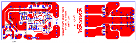
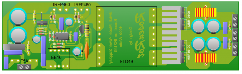
Its no meter... Now I wanna build SMPS 1KW with +-50V, IR2153, and ETD49 and IRFP460
I uploaded schematic and PCB and can enyone help me out with some questions!?
Unit with IRF730 is for IR2153 supply with zeners 15V (you can see that on board.. (can enyone see its good like that)
Board is small (real size is in PDF) and I found 1000uF 200V caps with 15mm diameter and 60mm high...
I have few questions:
1) Is my board good for this smps?
2) I can find in my country ETD49 core 3C90 and ETD49 core 3F3, which of these can I use, same question is for EE16 for curent sens?
3) Do I need air gap on central leg?
4) I dont know number of turns and wire ticknes for primary and secondary (I need +-50V)
5) Number of turns for EE16 current sens transformer and wire tickens?
I builded smps but i didnt have overcurent protect and everuthing blow up third time that i started
Its no meter... Now I wanna build SMPS 1KW with +-50V, IR2153, and ETD49 and IRFP460
I uploaded schematic and PCB and can enyone help me out with some questions!?
Unit with IRF730 is for IR2153 supply with zeners 15V (you can see that on board.. (can enyone see its good like that)
Board is small (real size is in PDF) and I found 1000uF 200V caps with 15mm diameter and 60mm high...
I have few questions:
1) Is my board good for this smps?
2) I can find in my country ETD49 core 3C90 and ETD49 core 3F3, which of these can I use, same question is for EE16 for curent sens?
3) Do I need air gap on central leg?
4) I dont know number of turns and wire ticknes for primary and secondary (I need +-50V)
5) Number of turns for EE16 current sens transformer and wire tickens?
Attachments
I have few questions:
1) Is my board good for this smps?
Looks just fine for startup project DIY
2) I can find in my country ETD49 core 3C90 and ETD49 core 3F3, which of these can I use, same question is for EE16 for curent sens?
I dont know about EE16, but 3C90 and 3F3 are best for SMPS, being used all over.
3) Do I need air gap on central leg?
hmmm, you have to ask HYPEX about this question indeed.
4) I dont know number of turns and wire ticknes for primary and secondary (I need +-50V)
Use calculator
5) Number of turns for EE16 current sens transformer and wire thickens?
I dont know about this!
Good Luck
hola compañeros tiene un esquemático de esa fuente que habla el amigo ap2 me gustaria para poder construirlo pues el comenta que es muy estable saludos desde colombia espero su respuesta

English please. Rules,
http://www.diyaudio.com/forums/site-announcements/167561-diyaudio-rules.html
Hello fellow has a schematic of this source which speaks the friend ap2 I would like to be able to build it because the comments that it is very stable greetings from colombia, I hope your answer
English please. Rules,
http://www.diyaudio.com/forums/site-announcements/167561-diyaudio-rules.html
Hello fellow has a schematic of this source which speaks the friend ap2 I would like to be able to build it because the comments that it is very stable greetings from colombia, I hope your answer
Last edited by a moderator:
Let me hijack this thread.
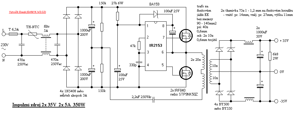
I did this setup Jednoduchý neregulovaný zdroj 2x 35V 2x 5A 350W pro zesilova?.
However it is not working.
I am using IR2153D. So I omitted BA159 diode.
On the first try I used a 60W bulb in series to the mains in order to avoid any blow up
Then I removed the bulb and ran the circuit directly.
I was not soldered the rectifier on the secondary. Just wanted to measure the AC on the secondary.
I got 50V on the secondary winding on transformer. After 1-2 second the voltage was 0V. After another few seconds it was again 45-50V.
Then I soldered the rectifier and ran the circuit again.
No success this time. 0V DC on the output.
Then I tried to debug it.
I have 0.25V on the gates on both mosfets.
I got 9V between pins 1 and 4 on the IC.
I think it should be 16V.
Do you have any clue ?
At 9v the IC goes to "undervoltage lockout".
Why do you have only 9v at pin 1?
Is the resistor Rvcc (27k 6W in your schema) OK?
Thank you for your prompt answer!
Used 22K/5W resistor.
Rectified voltage is DC 310V.
That makes 13mA current. I think is should be enough to operate the Zener Diode (inside the IC) at 15V.
I will de-solder all the connected pins but pins 1 and 4. Then I will measure the voltage across the IC.
If it is not OK then I will provide external 15V to feed the IC.
Let you know about the results.
As I ezplained the schematic is as follows:
Attached 40W incandescent lamp in series with the mains in order to prevent any issues.
In addition I put 0.47 Ohm 5W resistor in the source of LO side MOSFET in order to measure the current flowing.
I am using ATX PSU transformer.
Attached 12V bulb as a load to the secondary.
OK. Powered up and it worked.
However after few attempts the circuit stopped working.
I measured 8.9V between pins 1 and 4 of IR2153D.
Beside that I had build following circuit in order to test the IC.
After the SMPS failed to work I moved the IC to the test circuit. And it was not working.
OK. Replaced the IC with new one.
It worked several times and failed again.
Pin 7 is switching but pin does not.
Anyone has any clue ?
Attached 40W incandescent lamp in series with the mains in order to prevent any issues.
In addition I put 0.47 Ohm 5W resistor in the source of LO side MOSFET in order to measure the current flowing.
I am using ATX PSU transformer.
Attached 12V bulb as a load to the secondary.
OK. Powered up and it worked.
However after few attempts the circuit stopped working.
I measured 8.9V between pins 1 and 4 of IR2153D.
Beside that I had build following circuit in order to test the IC.
An externally hosted image should be here but it was not working when we last tested it.
After the SMPS failed to work I moved the IC to the test circuit. And it was not working.
OK. Replaced the IC with new one.
It worked several times and failed again.
Pin 7 is switching but pin does not.
Anyone has any clue ?
- Status
- Not open for further replies.
- Home
- Amplifiers
- Power Supplies
- SMPS IR2153 vs ATX transformers