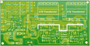
Hi to all. I draw this schematic and PCB layout for SMPS with IR2153 and ATX transformers P4
I take apart many ATX trans. and all are the same, only different is wire ticknes and size of ferrite core. Number of turns are the same.
I want to use 12V rails (without GND- that is 14turns) from trnasformer to get +-50VDC or more, changing the freq of IR2153. I use two pairs of IR2153 and Mosfet drivers IRF740 for two ATX trans, two bridges on secondary side.
For +15V to power IR2153, I use IRF730 with 330K and ZD15V on gate and ZD15 with 100uF and 100nF on sors.
Output bridges are 4xMBR10100 ich.
This is the best assumption that I had.
What do you think about this?
(One think more, on schematic, on primary side +marks are mistakes)
Attachments
You can use a single IR2153+MOS-FET's pair, even with 2 transformers. both primaries can be connected in parallel and secondaries in series with correct polarity to get +-50V or more. with a standard ATX smps transformer you can get about +-25V under heavy load and up to +-33V with no load. connect 2 of them in series to get almost double. use just 4 shotky diodes for rectification, and don't forget to add a ovecurrent protection scheme, otherwise all will blow up at short-circuit, or even at start-up due to the capacitors large inrush current.
further improvement which can be done, to increase the efficiency, if you could dismantle the transformer core and add a 0.3mm gap to decrease the magnetizing inductance to about 500-700uH and use a 0.22 uF series capacitor, then the transistors can work in zvs mode and they don't even need heatsink for up to 200-300W. the Rf resistor should be 10k only and Cf=1nf. you will have about 70Khz. the transformer will also run cooler due to lower flux and will get hot when the current draw will be high only, but for audio application, this is not a major concern, the peak-average ratio is high enough to not create significant temperature build-up.
further improvement which can be done, to increase the efficiency, if you could dismantle the transformer core and add a 0.3mm gap to decrease the magnetizing inductance to about 500-700uH and use a 0.22 uF series capacitor, then the transistors can work in zvs mode and they don't even need heatsink for up to 200-300W. the Rf resistor should be 10k only and Cf=1nf. you will have about 70Khz. the transformer will also run cooler due to lower flux and will get hot when the current draw will be high only, but for audio application, this is not a major concern, the peak-average ratio is high enough to not create significant temperature build-up.
Thank you Cristi and Kubeek.
@ Cristi: With one Ir2153, one pair of mosfet and two transformers, on 70KHz, how many voltage and current can I get?
Can I get +-50 60VDC and 500-600W with two transformers?
I need this for UCD amlifier D class +-50V on 2 ohm load for 500W RMS. Can this work?
I want build this strong as possible because I have lot ATX power supplys and in my country I cant find ferrite cores for other smps and Serbia is on black list for Farrnel, Ebay, paypal and others...
Thank you!
Last edited:
Can I get +-50 60VDC and 500-600W with two transformers?
Sure, if you rewind them. Then you can get whatever you want. You can pull 400W from one EI33 (typical cheap power supply core) but that's a bit on the extreme. On the other hand they will be quite happy doing 300W each so your 600W goal will be met.
The problem is that there are lots of variations, different supplies use slightly different transformers depending on operating freq and current output. The best way is to take them apart and rewind them. I'm sure you can find copper wire. 0.3mm wire is the most versatile wire i've used so far. Thin enough for winding GDTs on those little EE-16 cores, and when you need more current just put several strands and twist them together. Homemade litz wire.
")
If you need any info on winding the transformers, how many turns and so on, just let me know.
Can I simple increase swiching freq and use 5V winding without big gnd (thats 8 turns). 5V winding has 3x0.8mm wire, that means much more current than 12V winding where is 0.8mm single wire and 14 turns without big GND.
Original swich freq on atx smps is around 50KHz, if i increase to 90KHz, can I get +-50V on 5V winding and what about capacitor in serial with primary side to float? What is his function at all and value depending of swiching freq.
Thanks
Original swich freq on atx smps is around 50KHz, if i increase to 90KHz, can I get +-50V on 5V winding and what about capacitor in serial with primary side to float? What is his function at all and value depending of swiching freq.
Thanks
That "big gnd" is essential in a half bridge supply because it has full wave output - basically there's two identical secondaries that are rectified by two diodes into a single output. They are usually wound as a single winding with a center tap which is connected to ground. There's a little trick with the 12v output that allows it to not have that center tap.
If you increase switching frequency you get more losses in the wire. The output voltage remains the same because, since you haven't modified the transformer in any way, the primary to secondary turns ratio remains the same. The primary side capacitor is intended to block DC bias that could cause the transformer core to saturate and blow up the transistors. Remember, the windings' DC resistances are very low - the switching transistors see this as a high impedance only because of the inductance the core offers to that winding. When the core saturates, the inductance drops to zero and your transistors are essentially driving a short.
The capacitor depends more on maximum current than it does on frequency. Formula to calculate it is Ipk*Ton max/Vdroop, which gives C in uF. Where:
Ipk is peak current in primary of transformer
Ton max is maximum on time in uS - this is 1/frequency in kHz*max duty cycle*1000
Vdroop is allowed voltage droop thru the capacitor. This capacitor makes a waveform with "droop", it becomes no longer square but has a downward slope. The voltage drop of this slope should be no more than 10% of voltage at the primary caps, so it should be around 10-15v for a 230v mains powered supply.
You will see that this capacitor is undersized in most (if not all) computer PSUs, because it ain't cheap. Lower value of capacitor = higher voltage droop = higher primary current = more losses. You can simply use several in parallel to obtain a higher value. At 500W output a 4.7uF cap would be good. Needless to say, this MUST be a MKT/MKP type cap (you can try an electrolytic though, it'll be entertaining).
Last edited:
What could happen if amplifier in peak takes much more current than smps can produce, whether all blow up or what?
Well if you don't have any primary current limiting, the most likely failure is that of the primary transistors. Primary current is usually sensed thru the driver transformer if you're using bipolar transistors for power switches.
If the transistors aren't up to snuff they blow up. If the transformers aren't up to snuff, again, the transistors blow up.
One more question, how can i calculate disipation of mosfet drivers. whether there will be enough that little heatsink from PC smps without coler in amplifier case?
For a MOSFET dissipation is primary RMS current over RDS(on). Since there are two switches in a half bridge, you divide the value you got by two to get dissipation in each MOSFET. But, MOSFET RDS(on) is temperature dependent, so you should follow the datasheet graphs to find on resistance at the expected operating temperature. Btw, you have three major wrongs in your schematic.
1. The whole point of half/full bridge is full wave rectification, so why are you hooking up only half the transformer secondary? And you only need two diodes (or one double diode) per output. That's why you have a center tapped transformer.
2. No output inductor. High ripple and premature failure of the capacitors will be the result. Rod Elliot may be a good audio engineer but he certainly has no clue about switching power supplies.
3. No provision for regulation. Not only does the lack of regulation make a huge difference between idle and load voltages (SMPS transformers by themselves regulate a lot poorer than mains transformers), but it also forces you to use very large primary capacitors because all the mains frequency ripple will get thru.
For protection, you have that shutdown pin. How to use it is your business. As far as i can see the IR2153 does NOT support regulation. I'd just use a TL494 if i were you.
Next question would be how to calculate primary RMS current i suppose? You should really go read some books. I recommend "Switching Power Supply Design Third Edition" as the best starter book. It doesn't explain everything and has a habit of sending you back half the book to find a formula, but it's easy to understand.
PS. What layout software did you use? It looks neat.
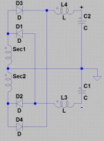
Here's one trick that will help you on your quest. Hook both transformer secondaries in parallel. Center tap and everything. Now, both rails will track each other perfectly.
But how to get positive/negative voltage with both windings in parallel you may ask? It might not be immediately obvious but check the attachment. The downside is that you're going to need diodes wired "the other way round" (common anode) for the negative rail. So, you'll have to use your double diodes as single ones. But i'm sure you have enough of them.
But how to get positive/negative voltage with both windings in parallel you may ask? It might not be immediately obvious but check the attachment. The downside is that you're going to need diodes wired "the other way round" (common anode) for the negative rail. So, you'll have to use your double diodes as single ones. But i'm sure you have enough of them.
Attachments
one suggestion,pls add soft start circuit for IR2153,this chip have not design soft start function ,maybe sometime cause hysteresis loop unilateral saturated.another choose is TL494 OR SG3525,SS function inside.
The reference using is YAMAHA 1000W powered mixer,works stable. but i forget the product type name.
Pass by this place,Only for reference.
The reference using is YAMAHA 1000W powered mixer,works stable. but i forget the product type name.
Pass by this place,Only for reference.
Hi,
certainly is not easy to develop effective protection for the 21531.
But since they wanted to use the 2151.
TL494 is good, Also you can add a driver eg. IR21xx or a transformer to drive the mosfet.
however I've solved the problem at the start of 21531. in the presence of a short circuit or high absorption. I enclose a pic just for curiosity. worked from 2002 until 2007 without problem in class H amps.
I think it works better, less RFI / EMI of some unregulated on the market.
somewhere in this forum I already put the diagram.
Attachments
Hi,
certainly is not easy to develop effective protection for the 21531.
But since they wanted to use the 2151.
TL494 is good, Also you can add a driver eg. IR21xx or a transformer to drive the mosfet.
however I've solved the problem at the start of 21531. in the presence of a short circuit or high absorption. I enclose a pic just for curiosity. worked from 2002 until 2007 without problem in class H amps.
I think it works better, less RFI / EMI of some unregulated on the market.
somewhere in this forum I already put the diagram.
IR2153D has several issues, beside start up and current protection
Lets see some videos of your SMPS, while you are shoring the Output?
or applying 290VAC at the input?
What will happen?
Hi,
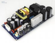
think the problem is focused on the current protection (especially during startup), not what happens when the VAC is 290. this can be solved in various ways, depending on how much to cost the psu. (this uses a varistor)
When I developed this smps, the company has asked two key parameters. compact low cost of production, big pulse current output, robust and reliable if they skip the mosfet amplifier.
This psu is very simple but has everything you need (I have not saved anything).
All outputs in the L-C filter.
well, how to solve that ir21531 have high UVLO and then, drives the mosfet already at full power? (IR21531 has no control DT Pin)
Then, becouse IR215xx is based on the 555, I can vary the duty cycle by varying the threshold on CX Pin. one BC337 and a few components involved in this function. Simple! at start, half bridge is unbalanced at low side, back slowly balanced if the output is free (not short out or over load) startup time 2 Sec.
Current protection out of startup, is very simple.
All you can fix , if you have experience, I think.
I have no time for a video but I assure you that thousands have worked for five years and has never exploded. (amps.. yes)
This PSU, current are out of production.
Regards
- Status
- Not open for further replies.
- Home
- Amplifiers
- Power Supplies
- SMPS IR2153 vs ATX transformers