One of my friends just gave me an Onkyo TX-DS474(Dolby Digital Receiver) purchased in the US. But I live in here in Singapore where the voltage is 230V.
I could see this TX-DS474s were manufactured in 3 configurations, a US model with 120V, European/Australian Model with 230V and finally a "Worldwide" Model with switchable 230/120V option .
Since I come from a consumer electronics MNC background, I have seen in our company products with almost similar PSUs(PCBs same, components not populated) but featured disabled when such operating voltage differences are found across models.
Anyway I decided to open it up and I did find some 230V markings inside the PSU input PCB. I also found
something like a second input for the transformer, which could be actually for 230V input?
But the problem is I haven't worked on anything electronics for a while now, being the embedded software guy I am... So I am not sure how to safely test for such options? I also don't know, whether I need to depopulate or repopulate any components...
Attached are the pictures... If anyone could give me some pointers, or identify te circuit or has schematics, it will be a great help. Or do you think going with a 230V-110V stepdown transformer is the way to go?
Thanks
Ron
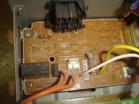
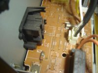
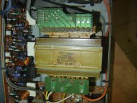
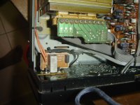
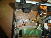


More pictures
I am looking for a service manual and schematics now... One quick question... if I have to test that suspected transformer primary 230V input with out schematics, how shall I proceed?
De-solder all the secondary and Primary output and connect 230V to that suspected primary input and measure the secondary voltage? then repeat the same with with 110V through another stepdown(230V to 110V) converter? Is that the way to go? or some other better options? I don't want to electrocute myself after all
Appreciate your inputs...
Attached are some closeup snaps of the board and primary...
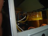
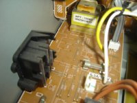
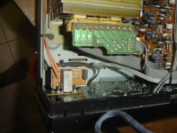
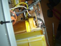


It's hard for me to tell from the pics because it looks like there are 4 connections on the primary winding. You might be able to visually inspect the primary side to see if it has the unused 230V windings. Use an ohmmeter to measure what looks like "2 halves" on that primary side.
If you already have a 230-110 I'd step-down, then use it on the primary. The 230V winding will give only half the normal secondary voltage, and it's a bit safer than feeding it 230V.
If you already have a 230-110 I'd step-down, then use it on the primary. The 230V winding will give only half the normal secondary voltage, and it's a bit safer than feeding it 230V.
service manual can be downloaded here TX-DS474 service manual download for Onkyo Radio fix technical repair instruction schematic diagram free : GiveMeFile.Net (I wouldn't click on anything that asks you to check your computer for outdated drivers though, as I'm wary of that sort of thing).
Not sure if it will help though, a quick glance and I was none the wiser with respect to the transformer, except that the circuit diagram only shows a single primary... and it also appears that there is a second mains transformer which is rectified to provide voltage to drive a relay to switch the main transformer... Sort of a soft switch if you will, so you will need to take that into consideration as well.
Tony.
Attachments
The download looks legit, but I've reuploaded it on MedaFire for the paranoid -
TXDS474sm.pdf
The schematic only shows how it is electrically wired up though, the places for the 230V fuses and stuff are still on the PCB, only unused or jumpered. The main transformer may physically be 115/230V capable although the schematic of the single-voltage version suggests otherwise. (The sticker on the physical transformer has a 'D' suffix suggesting dual-voltage type as used in the schematic as opposed to plain 1360 used for single-voltage versions)
Same goes for the smaller transformer - it also has 4 connection points at the primary side and the 'D' suffix. You'll have to rewire that too.
You can connect a speaker amplifier to the transformer (or even via the mains cable of the amp). Play into the transformer a 50Hz signal generated by Audacity at a low voltage, say 1V (use a multimeter in AC voltage mode to measure). The other side you should be able to measure some voltage - it won't be precise since cheap meters only measure up to 0.1V for AC, but good enough for the task. Rewire until you get half the voltage at the secondary compared to at first. And change that fuse to a lower-current 250V one.
Prepare to remove that board as it doesn't seem possible to rewire the smaller transformer without doing so.
- Status
- This old topic is closed. If you want to reopen this topic, contact a moderator using the "Report Post" button.