I've simmed my LM317 supply to death, I've obsessed over the component choices, and now surprise surprise I'm obsessing over the layout....
Get the impression I tend to be a bit obsessive?
So I'm doing it on Verro Board, no plan to make a PCB. The original idea of using LM317's for both the positive and the negative rails was to ensure the same characteristic for both rails. To ensure symmetry so to speak.... I'd read (and you never know if you can trust what you read on the Internet") That LM337's aren't as good as LM317's so that was why I decided to make a PS with LM317's only. For some background you can visit my blog page on this supply
That LM337's aren't as good as LM317's so that was why I decided to make a PS with LM317's only. For some background you can visit my blog page on this supply
So the problem I have run into is that since I'm using two LM317's rather than an LM317 and an LM337 when it comes to the layout, making it symetrical is VERY hard, especially when doing it on Verro Board. (well it is for me anyway, perhaps layout isn't one of my strong points)...
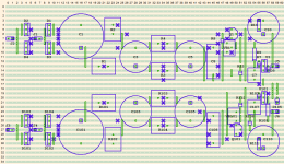
So I've tried for a long time to come up with something that approximates a good layout. I originally just had the same layout for +ve and -ve but the supply wires were too far apart. Then I decided to start at the outputs and work my way back, trying to keep the outputs of the LM317's as close to the wiring points as possible.
Anyway attached is the layout I've come up with. The reg end of R7 and R107 will actually be soldered directly to the pin of the reg close to the body. and I may also run a wire directly from pin three on the pots to the star earth point rather than the link on the board (the star earth point will be a bolt in the middle of the board between the +ve and -ve connectors). They are probably the two most important layout considerations, based on my understanding of the data sheets.
So for my first attempt at a layout for an LM317 based reg circuit, am I doing ok? should I stop obsessing and just build the thing? I Haven't yet revised where all of the cuts will be, that needs some tuning (and there may be some redundant ones that I haven't removed after changing things around).
I'm most interested in whether the subtle differences between the +ve and -ve parts of the circuit are anything to worry about, or more importantly if there is anything glaring that will be likely to cause me grief!
ps R11 and R111 are surface mount in case anyone wondered.
Tony.
Get the impression I tend to be a bit obsessive?
So I'm doing it on Verro Board, no plan to make a PCB. The original idea of using LM317's for both the positive and the negative rails was to ensure the same characteristic for both rails. To ensure symmetry so to speak.... I'd read (and you never know if you can trust what you read on the Internet
That LM337's aren't as good as LM317's so that was why I decided to make a PS with LM317's only. For some background you can visit my blog page on this supply So the problem I have run into is that since I'm using two LM317's rather than an LM317 and an LM337 when it comes to the layout, making it symetrical is VERY hard, especially when doing it on Verro Board. (well it is for me anyway, perhaps layout isn't one of my strong points)...
So I've tried for a long time to come up with something that approximates a good layout. I originally just had the same layout for +ve and -ve but the supply wires were too far apart. Then I decided to start at the outputs and work my way back, trying to keep the outputs of the LM317's as close to the wiring points as possible.
Anyway attached is the layout I've come up with. The reg end of R7 and R107 will actually be soldered directly to the pin of the reg close to the body. and I may also run a wire directly from pin three on the pots to the star earth point rather than the link on the board (the star earth point will be a bolt in the middle of the board between the +ve and -ve connectors). They are probably the two most important layout considerations, based on my understanding of the data sheets.
So for my first attempt at a layout for an LM317 based reg circuit, am I doing ok? should I stop obsessing and just build the thing? I Haven't yet revised where all of the cuts will be, that needs some tuning (and there may be some redundant ones that I haven't removed after changing things around).
I'm most interested in whether the subtle differences between the +ve and -ve parts of the circuit are anything to worry about, or more importantly if there is anything glaring that will be likely to cause me grief!
ps R11 and R111 are surface mount in case anyone wondered
. Tony.
Attachments
Thanks Andrew! I can probably most easily do that with a fly lead (of minimum length possible) I was planning on putting a small bolt in at the common zero volts point for runs to the circuit it is powering so could have it as another lead connecting to that point.
Does that sound reasonable, or do you think I should I try to do it using the tracks on the board? Whilst not a novice when it comes to making circuits on verro board, I am a novice when it comes to layout, it is something I was blissfully unaware of for a very long time
Tony.
I can probably most easily do that with a fly lead (of minimum length possible) I was planning on putting a small bolt in at the common zero volts point for runs to the circuit it is powering so could have it as another lead connecting to that point. Does that sound reasonable, or do you think I should I try to do it using the tracks on the board? Whilst not a novice when it comes to making circuits on verro board, I am a novice when it comes to layout, it is something I was blissfully unaware of for a very long time
Tony.
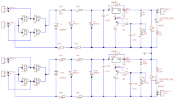
break the connection between the bottom of C5 and the bottom of C7.
Now connect the junction of C5 & R4 direct to the Zero Volts commoned output terminal. Your bolted Zero Volts would do, but simply soldering the Zero Volts Power Rail to the output terminal will do. Repeat for C105 etc.
Note that C7 is required close to the regulator input pins (both of them). Separating the Power Line from C7 demands that C7 must be installed. Else the route around the loop becomes far too long and could lead to instabilities, no matter that the +ve feed lead is kept very short, it's the total loop length that matters.
Last edited:
OK thanks Andrew yes that makes more sense . I'll leave C7 where it is (unless you think it should be right on the pin, which would require me to change to a different cap, perhaps an NPO ceramic...
After my experiments I've pretty much decided to drop the 10mF caps and change to 4700 4700 1000, so will have a bit more space to play with and will probably compact the layout a little, giving me a bit more room to move at the output end of the board.
Tony.
After my experiments I've pretty much decided to drop the 10mF caps and change to 4700 4700 1000, so will have a bit more space to play with and will probably compact the layout a little, giving me a bit more room to move at the output end of the board.
Tony.
- Status
- This old topic is closed. If you want to reopen this topic, contact a moderator using the "Report Post" button.