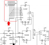
In the attached schematic fragment, it's circled in red. "Phase" is treated as "delay" ; the MC14557's delay is adjusted. The six dipswitches on the left provide fine_adjustment, and the two dipswitches on the right (@ pins 10 & 11) perform coarse_adjustment.I don't see a phase offset adjustment on yer diagram? I would of used a common CMOS Schmidt trigger instead of a linear +/- circuit.
.
.
Attachments
Sync, I am curious if you built it. ")
Destroyer, Zig, Others,
I'm doing this...
Question is it this what you meant by crossing the wires over?
quick and dirty schematic...
An externally hosted image should be here but it was not working when we last tested it.
Those film caps will all resonate with each other and sing up a storm. Say you have 22nH loop area around a 100nF cap. That gives a terrible resonance at 10MHz. Now you got a bunch of different value caps with no dampening at all. Crossing the wires will cause the magnetic fields to cancel somewhat, but all that does is lower the inductance and shift the resonance to a higher frequency.
These things really need to be measured with a signal generator and scope, because modeling it accurately in simulation by estimation takes much longer than building a prototype, and there are so many opportunities to mess the whole simulation up by doing one thing wrong.
A quick and dirty fix would be to make an RC with a cap 3-5 times the largest filter cap, with a highly non-inductive (carbon comp) resistor of around .5R-2R. This resistor must have high surge capacity (carbon comp) and must have high enough wattage, and this tends to limit you to less than 1uF unless you use several parallel resistors (which will be wasting some heat). The cap should go next to the smallest filter cap, as that one will have the highest resonance frequency and will need to be closest to the dampener for low inductance.
Also, don't make the mistake of using high-Q capacitors here. High Q is fine as long as it is also the lowest ESL. But at RF ESL completely swamps ESR. Choose caps with closer pins and smaller bodies. Polypropylene has high-Q but is larger which almost always means more ESL. MKT is better in this respect. Use the physically smallest cap you can find, relatively high ESR will just mean you won't have to use an expensive dampening RC.
The CM choke is helpful, but it will resonate with the transformer leakage capacitance, which can have the opposite effect you want. A 2.2k resistor across each coil is a good value, but again this is not hard to measure.
Kemet has the PMR series of film capacitors which already have a resistor inside. These are a kind of suppression cap, for when suppression is about dampening, which is more often then not. I haven't found a suppression cap with a 0.5R-2R resistance though. Usually it is 22R or 47R or something like that, so these aren't optimal for a filter like this.
Do you know what kind of heat a resistor makes across line? At 2.2k a 50w resistor needs a heatsink of sorts. Even then it won't be cool.
Common mode noise is generated from transformer inner capacitance; being exactly what a CMC is designed to help with. In and out common mode noise is an issue.
Perfect or not, there's an lot of anecdotal evidence they work leagues ahead of nothing. Your the first person to really proclaim "major" issues, out of multiple engineers.
Also they are parallel so the resonate frequency isn't a massive concern unless it's at an actual RF frequency common in radio, as it will tend to be narrow, and the filter will reject it. Also don't forget ESL and ESR drop with each capacitor added.
Sure, it's better than nothing. That filter will work, but perhaps not optimally and may be susceptible to interference at the resonant frequencies. What happens if the resonance just happens to fall on the frequency of some nearby appliance? EMC journals are full of stuff like that.
The 2.2k resistors are not across the line, they are across the CM choke coils. If they have much voltage across them, your coil is fused and they are the least of your worries. A real fuse should prevent this.
How do you put 10mH in series with a 100p capacitor without getting a series resonator? I've studied the impedance charts for CM chokes, and they have no significant self-damping, they resonate by themselves at 400KHz or so. I've measured this in real life and it's in the datasheets. It is a CM resonance, so it has the opposite effect as intended at the resonant frequency - a reactance null which means nearly a dead short at the resonant frequency, and the current passes through every parallel ground loop, including your audio source.
Does it matter? I thought it made an audible improvement. I may just be fooling myself, so do your own experiments.
ESL drop with parallel capacitors doesn't matter because it's the ESL of the larger capacitor that resonates with the lower capacitor. I just measured a chip amp board which had a very innocent 2200u cap bypassed with a 100nV cap. It resonated with about 7 visible cycles on the scope. This happens unless the ESL of the 100n is at least 5 times higher than the ESL of the lytic, but then the bypass is pointless. The resonance was at 3.3MHz. Feedback amplifiers have very low PSRR at those frequencies, so rail impedance and PSRR add to make stability dependent on rail impedance. Some people take advantage of this to modify the stability of their amps, although they may not realize this is what they are doing. An amp won't react this way to resonances at the power filter, but it is an example of how easy it is to make a resonator that results in much exasperation and head scratching ("but I used all the best High-Q caps!") unless one is fully informed.
I don't think I'd worry about capacitor resonance. You're talking thousands of difference in size vs small fractions. It seems the closer in size, the less resonance issues. There's countless commercial amplifiers of the lowest to highest quality that employ farther ranged caps, but won't employee the mythical tiny bypass.
CMC however, that's interesting.
CMC however, that's interesting.
Even if the caps are different by a factor of 2, for instance 100n/200n, the resonance is hardly affected. Purely reactive components don't have loss, so they will resonate no matter what if there is no damping elsewhere in the circuit. Even bad film caps are extremely good at this. Again, this can be measured if you have a scope and a signal generator (10nS risetime).
Another thing you can do to effectively dampen all resonances, is to make a sort of discrete transmission line from caps. You just use the exact same cap in parallel in a long string from input to output. The resonances will all be the same and it will have transmission line-like properties. This means you can put the right termination RC at the end and all resonances will be damped. You can design the line to have a specific dampening resistance by adjusting the spacing between caps. I think if you did this with the above filter, using 22 cheap 100n caps, you may have something better.
Anyways, I can go on about my ideas to theoretically improve a line filter. I don't want to get creepy about it though, there are a lot of other things that are more important I think.
I'd argue almost nothing is more important. If I had the choice of straight AC with equipment that doesn't have line filtration, or no stereo, I'd pick no stereo. Simply, I do not listen to stereo's without line filters unless they're battery operated. It's not worth it, it's fatiquing and simply a waste of my time.
Generally any noise on the line will appear as a rise in impedance, so would that not create some dampening? Otherwise if there's no noise, there isn't much to resonate besides the filters self factors.
BTW I only use the same size capacitors in my actual conditioners, on either side.
Generally any noise on the line will appear as a rise in impedance, so would that not create some dampening? Otherwise if there's no noise, there isn't much to resonate besides the filters self factors.
BTW I only use the same size capacitors in my actual conditioners, on either side.
Last edited:
Destroyer OS.
Clicking on your User Name gives incorrect profile.
I know, it's annoying since I can only use "subscribe" feature via emails to find posts I've made.
Destroyer OS.
Clicking on your User Name gives incorrect profile.
I know, it's annoying since I can only use "subscribe" feature via emails to find posts I've made.
Its because of the . (dot) in the name. If you want it altering (no dot) then let a moderator know and it should be possible to change it.
Its because of the . (dot) in the name. If you want it altering (no dot) then let a moderator know and it should be possible to change it.
Actually
that won't work because you can't send pm's in your name. If you want it changing post in this thread and I'll see if an "admin" can do it.Could someone please explain to me what these two sentences mean? Are we talking common-mode noise (typically from radiated interference, such as nearby cell-phones or radio stations) or differential-mode noise (typically from conducted interference, such as poorly-suppressed SMPS in the same house).Destroyer OS. said:The noise's impedance (source) tends to be high. It improves the Q factor, where as just purely source impedance of the power from your substation tends to be low, leaving Q less desirable.
DF96,
That's mostly in reference to what's on the line, vacuums, smps, you name it. However as you know your power distribution can pick up some stuff in the air. Anyway, typical source noise, say a light bulb, is higher impedance as you can imagine. LC filters, like the CMC and suppression caps can filter more when Q increases, which happens as source impedance rises. On the other hand it goes down the more the loads impedance goes up.
But what I want to know is whether source impedance that's resistive, some noise maybe from LED light bulb or something, acts to dampen an LC filter.
Half of the problem with all of this is that nothing is consistent on the line, so modeling and what not has been a hot debate.
The noise source has its own impedance, this is what he seems to be saying. The power socket has a mostly inductive impedance. This website doesn't consider skin effect, but it has some useful ideas on mains noise:
Just one thing about music - when it hits you feel no pain
Just one thing about music - when it hits you feel no pain
- Status
- This old topic is closed. If you want to reopen this topic, contact a moderator using the "Report Post" button.
- Home
- Amplifiers
- Power Supplies
- How to make a power conditioner