You don't say how your transformer test circuit is connected, is it possible that DC current is saturating the core and skewing the measurements? This could cause errors that depend on regulator current consumption.
We use an active driven source to feed the input rather than a transformer, and are working on a PSRR test circuit that uses an LM3886 to drive the input with DC+AC.
The transformer isn't saturating -- it's good up to about 600mA DC. See Audio Precision TN-106.
I use the 1995 TAA Articles as a reference point. Jung specified a load of 100R//100uF. You may be using a purely resistive load.
I've used batteries, an HP6271B and a Tek PS5010 to drive the regulators. The HP6271 can be "modulated" but it requires de-racking it.
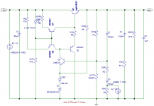
The output impedance of the AP2722 is 20 ohms unbalanced, 40 ohms balanced. The schematic below shows a low impedance driver WJ used for his experiments which overcome this issue. (It's a variant of the Pooge 5.1 regulator). I simmed it to be ~2.4 milliOhms. Variously, WJ appears to have used 1.4V p-p and 1V p-p, for his line rejection tests. Using 1V RMS is putting a lot more burden on the regulator, I agree.
Line rejection is easier to measure than output impedance. The noise tests use a balanced, low noise line driver set to 100X.
For the diode example you give, do you want to specify the diode and leakage inductance of the trafo you were using? Almost looks like my wife was using her hair blower!
An externally hosted image should be here but it was not working when we last tested it.
@belleson
post #35, second picture with measurement results: are you using HPF ?
The FFT software has a "Remove DC" selector which is active. I also believe the hardware used for this measurement has an input coupling capacitor.
The output impedance of the AP2722 is 20 ohms unbalanced, 40 ohms balanced. The schematic below shows a low impedance driver WJ used for his experiments which overcome this issue. (It's a variant of the Pooge 5.1 regulator). I simmed it to be ~2.4 milliOhms. Variously, WJ appears to have used 1.4V p-p and 1V p-p, for his line rejection tests. Using 1V RMS is putting a lot more burden on the regulator, I agree.
The low impedance driver is exactly the topology we used in PSRR tests, except of course the modulated regulator is a Superpower. The problem with this topology is the limited output frequency. This positive regulator, with load capacitor C2=0.1uF and load resistor R12=350 Ohms, can go to about 42KHz before the negative going signal starts to limit. With 1uF on the input of the DUT regulator, frequency limits at 4.2KHz, 10uF/420Hz, etc.
This is because the output has an active current source but a passive current sink limited by the 350 Ohm R12. When Vout modulation peaks and begins to decrease, R12 has to discharge C2 and any capacitance on the DUT input. This is why our PSRR measurements go only to 5KHz and why we're looking at a different driver such as LM3886, which can sink as well as source current.
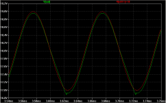
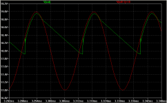
At f(max), the sine wave does not degrade gracefully into a triangle but instead the low-going half-wave slew limits and decreases Vmax amplitude, distorting the measurement reference value of 1Vpp (or in your test 1Vrms).
For the diode example you give, do you want to specify the diode and leakage inductance of the trafo you were using? Almost looks like my wife was using her hair blower!
I don't know the transformer and diode leakage inductance, it's the raw output from the rectifier in a Tripp-Lite PR-10b. The "hair blower" spectrum is typical of (approximately) sawtooth full wave rectifier ripple, only the textbooks don't show so many harmonics.
Last edited:
The problem with this topology is the limited output frequency. This positive regulator, with load capacitor C2=0.1uF and load resistor R12=350 Ohms, can go to about 42KHz before the negative going signal starts to limit. With 1uF on the input of the DUT regulator, frequency limits at 4.2KHz, 10uF/420Hz, etc.
R12 is in parallel with the sense network (2.43K +1.82K), so the pole is closer to 5kHz. R1,C1 is a zero @655kHz.
Here is the response of the Rail Driver without compensation:
An externally hosted image should be here but it was not working when we last tested it.
and with compensaton:
An externally hosted image should be here but it was not working when we last tested it.
Everything looks better with the Jung regulator driver -- it's pumping out at 18V. The Belleson, indeed looks much, much better with this setup. I think I was over-driving all of these regulators with way too much ripple.
This is, essentially the setup I'm now using to measure LR.
This is, essentially the setup I'm now using to measure LR.
An externally hosted image should be here but it was not working when we last tested it.
Last edited:
The LM317 was tested with Cin=0.1uF, Cref=10uF, Cout=1uF, R1=270 Ohms, R2=2K Ohms, Vin=30V, Vout=10.8V. An 8 Ohm load was switched from Vout to ground using a D880-Y power NPN. The SPJ Superpower uses a standard D44H11 or D45H11 output transistor.
If you are planning to use regulators in parallel, I suggest the LT3080 or something similar, not LM317.
Brian,
The LM317 setup seems reasonable and I find your suggestion to use an LT3080 refreshingly honest (although it still is an expensive IC).
Thank you.
--
Greetz,
MatchASM
R12 is in parallel with the sense network (2.43K +1.82K), so the pole is closer to 5kHz. R1,C1 is a zero @655kHz.
Here is the response of the Rail Driver without compensation:
{images clipped}
This is fine, but it's not a bandwidth problem it's a slew rate problem. If the tested regulator has any capacitor C5 on the input, as some require for stability, this affects the negative slewing of the rail driver output. The maximum negative slew rate is set by
dV/dt = 2pi(f)Vmax where Vmax=Vpk of the sine wave (not pk-pk)
Current I5 flows into and out of C5 as the rail output oscillates:
I5 = C5(dV/dt), and the dV/dt is set by I5 = Vout/R12
Combine these and you get
Vout/R12 = 2pi(f)(Vmax)(C5)
You can plot C5 vs. f to see the maximum clean sine frequency per uF, or choose a value for C5 and plot the maximum sine amplitude vs. frequency.
The two oscillogram simulations are using C5=1uF, the first is at 10Khz and you can see the linear slew of the green Vout as it hits the limit (red is the modulation signal V2). The second one is 40KHz and the output barely makes it back to mid-scale before the next cycle comes along. This is what I was referring to in post #45 when I said the test signal to the DUT is no longer a valid amplitude, nullifying the resulting measurements w.r.t. 0dB.
Note that V2 was inverted and scaled by +18Vdc to be visible and compared to rail driver Vout.
This is much less of a problem if the tested regulator has no input capacitor, but you have to be careful.
Attachments
Last edited:
The effect of C5 (which isn't part of the modified POOGE 5.1 used as the rail driver) is shown with this "pulse" instead of sine perturbation.
The compensation scheme for the 1N4148+BZX846V2L is probably going to be a different from that used for the LM329DZ:
An externally hosted image should be here but it was not working when we last tested it.
The compensation scheme for the 1N4148+BZX846V2L is probably going to be a different from that used for the LM329DZ:
An externally hosted image should be here but it was not working when we last tested it.
The effect of C5 (which isn't part of the modified POOGE 5.1 used as the rail driver) is shown with this "pulse" instead of sine perturbation.
Yes, same effect, different view. A pulse is not applicable to the PSRR discussion. I stated C5 represents capacitance on the input of the tested regulator. My 20+ years of integrated circuit design and testing of op amps, regulators, micro-machined sensors, track/holds, high accuracy A/D and D/A converters, et al have shown many times that neither the test equipment nor the device under test can be considered in isolation, but instead must be developed and measured as a system.
The compensation scheme for the 1N4148+BZX846V2L is probably going to be a different from that used for the LM329DZ:
Yes, I used available simulation components to get the same Vout. This also does not apply to the discussion of PSRR testing with a unipolar source driver.
jackinnj,
After reviewing your test diagram in post #48, I see that you do NOT have an input capacitor on your test circuit so my comments about C5 relate to our test setup and not yours. That tangent about slew rate distortion of the sine wave can be considered an intellectual exercise for the interested reader") . Nonetheless, I suggest care when measuring out to 200KHz, as it doesn't take much capacitance at that frequency to distort the input signal.
. Nonetheless, I suggest care when measuring out to 200KHz, as it doesn't take much capacitance at that frequency to distort the input signal.
Thanks for rearranging your setup and re-testing.
Brian
Belleson, LLC
After reviewing your test diagram in post #48, I see that you do NOT have an input capacitor on your test circuit so my comments about C5 relate to our test setup and not yours. That tangent about slew rate distortion of the sine wave can be considered an intellectual exercise for the interested reader
. Nonetheless, I suggest care when measuring out to 200KHz, as it doesn't take much capacitance at that frequency to distort the input signal.Thanks for rearranging your setup and re-testing.
Brian
Belleson, LLC
OK, I think these results are more consistent with what you found -- the DSP Analyzer has a much narrower bandpass filter than the Analog Analyzer. The A/B test in Analog Mode can't be run in Bandpass Mode without writing a macro.
I pulled out the National Semiconductor LM7805 Datasheet and ran the test with an STMicro LM7805 and a whopping 3.5V RMS -- they show LR of -82dB and my result is -78dB.
The other tests were done with 1V pk-pk. The test with the Super Regulator used an AD825 error amplifier (not decoupled) and LED biasing so the results aren't quite consistent with the 2/95 TAA article. And, after all, the Super Regulator is a lot more complex.
Attachments
Last edited:
We finished our new ripple rejection test fixture yesterday and there is good news and bad news. The good is the measurements are much better, we're measuring DUT performance more accurately and not so much the characteristics of the test fixture, e.g. AC feedthrough.
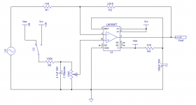
The new fixture uses a DC+AC driver based on the LM3886 as seen in the attached schematic. The 3886 has wide bandwidth, sufficient output power and slew rate to deliver a high frequency sine wave on top of a DC voltage.
To see how Superpower stacks up against other commercially available regulators, 3 other regulators were tested. We did direct comparison measurements by setting up the fixture, calibrating Vin and frequency and plugging in each of the regulators in turn. Vin=16VDC+1VppAC, Vout=12V with DC load of 240 Ohms. (Vout=9V for Dx7809). Output current is 50mA except for Dx7809 where it is 37.5mA, to be fair to the regulators that cannot deliver high currents. Vin AC was calibrated after each frequency change.
Two measurement systems were used, a 24 bit differential input A/D with 20KHz bandwidth and a 16 bit 195K sample/second A/D. Both were calibrated to a 4 3/4 digit true RMS DMM and correlated to each other on 10KHz and 19KHz measurements where the ranges overlap and measurements were available. Measurements were made from 100Hz to 600KHz, changing from the 24 bit A/D to the 16 bit between 19KHz and 50KHz. The 600KHz point was made with the magic of aliasing (a.k.a. undersampling), where the "carrier" folded back into the baseband at about 15KHz.
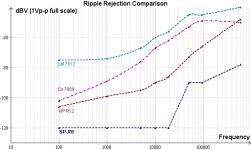
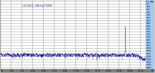
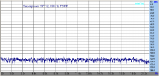
The bad news is that you probably won't believe the results--I had to triple-check to believe it myself. Superpower PSRR is essentially in the noise of each respective measurement system below 600KHz, where it still measures a respectable -78dBV. For what it's worth, a comparison graph is attached and a spectrum at 19KHz. A 19KHz LM7812 spectrum is also attached as a baseline reference to show that indeed the test fixture does work. We will have an updated web page on our site by next week.
The new fixture uses a DC+AC driver based on the LM3886 as seen in the attached schematic. The 3886 has wide bandwidth, sufficient output power and slew rate to deliver a high frequency sine wave on top of a DC voltage.
To see how Superpower stacks up against other commercially available regulators, 3 other regulators were tested. We did direct comparison measurements by setting up the fixture, calibrating Vin and frequency and plugging in each of the regulators in turn. Vin=16VDC+1VppAC, Vout=12V with DC load of 240 Ohms. (Vout=9V for Dx7809). Output current is 50mA except for Dx7809 where it is 37.5mA, to be fair to the regulators that cannot deliver high currents. Vin AC was calibrated after each frequency change.
Two measurement systems were used, a 24 bit differential input A/D with 20KHz bandwidth and a 16 bit 195K sample/second A/D. Both were calibrated to a 4 3/4 digit true RMS DMM and correlated to each other on 10KHz and 19KHz measurements where the ranges overlap and measurements were available. Measurements were made from 100Hz to 600KHz, changing from the 24 bit A/D to the 16 bit between 19KHz and 50KHz. The 600KHz point was made with the magic of aliasing (a.k.a. undersampling), where the "carrier" folded back into the baseband at about 15KHz.
The bad news is that you probably won't believe the results--I had to triple-check to believe it myself. Superpower PSRR is essentially in the noise of each respective measurement system below 600KHz, where it still measures a respectable -78dBV. For what it's worth, a comparison graph is attached and a spectrum at 19KHz. A 19KHz LM7812 spectrum is also attached as a baseline reference to show that indeed the test fixture does work. We will have an updated web page on our site by next week.
Attachments
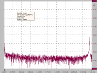
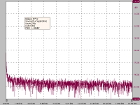
Adding the 19KHz spectra from the 24 bit A/D for LM7812 and Superpower to show we get the same answer 2 ways, with a lower noise floor.
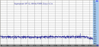
Adding a "sanity check" where Vin is increased to 2Vp-p, with visible supply feedthrough at approx -110dB.
To CraigBuckingham:
The 90MHz oscillation could have been RF picked up by the AD797 or some artifact of the breadboard. We were interested in output dynamic current delivery so once we got the Iout-dependent oscillation tamed, we took our measurements and moved on.
Attachments
The link to the ALSWR on the page referenced by Craig is broken - here's one that works:
http://www.connect-audio.co.uk/Regulator/ALWSR.pdf
http://www.connect-audio.co.uk/Regulator/ALWSR.pdf
The link to the ALSWR on the page referenced by Craig is broken - here's one that works:
http://www.connect-audio.co.uk/Regulator/ALWSR.pdf
Updated, thanks!
Here is the patent application for the Belleson regulator. You can click the Documents tab to get the complete 23 page application:
US2010037556 VOLTAGE REGULATOR USING DEPLETION MODE PASS DRIVER AND BOOT-STRAPPED, INPUT ISOLATED FLOATING REFERENCE
Interesting design.
US2010037556 VOLTAGE REGULATOR USING DEPLETION MODE PASS DRIVER AND BOOT-STRAPPED, INPUT ISOLATED FLOATING REFERENCE
Interesting design.
- Status
- This old topic is closed. If you want to reopen this topic, contact a moderator using the "Report Post" button.
- Home
- Amplifiers
- Power Supplies
- The Belleson Superpower, the ultimate voltage regulator ... ?