Rewind the transformer primary for 13 turns. For 50V secondary you need 4 turns. Then measure the leakage inductance and the magnetizing inductance.
Then we can move forward.
I have rewound primary to 13 turns and secondaries to 4 turns.
This gives (with no gap) 200uH and 96uH
What next ?
I have rewound primary to 13 turns and secondaries to 4 turns.
This gives (with no gap) 200uH and 96uH
What next ?
According to the ferrite datasheet, your total primary inductance should be 752uH with 13 turns and no gap. According to my approximations your leakage inductance should be about 15-30uH.
So there must be some problem with your winding or your measurement. Could you make a close picture about your transformer winded?
Last edited:
According to the ferrite datasheet, your total primary inductance should be 752uH with 13 turns and no gap. According to my approximations your leakage inductance should be about 15-30uH.
So there must be some problem with your winding or your measurement. Could you make a close picture about your transformer winded?
The core material is 3c90.
I checked my LC meter with some known inductors and it reads OK.
An externally hosted image should be here but it was not working when we last tested it.
Last edited:
According to the ferrite datasheet, your total primary inductance should be 752uH with 13 turns and no gap. According to my approximations your leakage inductance should be about 15-30uH.
So there must be some problem with your winding or your measurement. Could you make a close picture about your transformer winded?
Bu that would give a k factor of 25 when the recommended k factor is 3 to 10.
According to the ferrite datasheet, your total primary inductance should be 752uH with 13 turns and no gap. According to my approximations your leakage inductance should be about 15-30uH.
So there must be some problem with your winding or your measurement. Could you make a close picture about your transformer winded?
I was getting about 700uH with 36 turns so I wont get it with 13 turns.
In fact scaling the turns down does give what my meter is saying.
And the secondaries are the same number of turns so no change there which again sounds correct.
I used the transformer as you suggested.
I worked out Cr as 100nf.
I powered up the SMPS and it outputs +/- 50 volts DC.
I need to do some more testing on loads to make sure it works ok.
Nigel, your transformer is seriously not ready.
It wont work OK, it can even destroy the FETs and the controller.
Ferroxcube ETD54 made of 3C90 has an Al of 5000nH. So your 13 turns should have a total inductance of 845uH without a gap.
Your transformer is very ugly wound, and the distance between your primary and scondary is almost 1 cm. Just try to move the secondary a bit closer (aobut 2mm) to the primary, your leakage inductance will decrease rapidly.
We arae aiming a leakage inductance of 15-30uH. After we get something like this, we apply a gap to set tha magnetizing inductance, tog et a proper k value. Setting the magnetizing inductance is the last (since it is easy).
However if your meter reads a different value than we calculate from the datasheet of the ferrite core and the turns, we must think on "Where is the error?", because it can be caused by the following:
- ferrite half cores ar not grinded
- you dont push them together when measureing (it is just a measurement problem, it will not cause us harm, however we must check it to rule out other errors)
- there is a magnetic pathway short
- there is some problem with the wire insulation, its leaking
So better check out.
Also you are using thick wire with only one strand. Unfortunately I do not have a picture of my transofrmer without the yellow insulating tape, however I can show picture about a nice wound transformer.
As you can see it uses multiple strand of thin wire to mach currents. Look at how nicely it is wound.
I found an old etd34 core and wound 13 turns on that to see what I get.
I get 20uH !
I checked my meter and that is fine on some inductors I had lying around.
I took out the cores on my original transformer and turned them 180 degrees.
I now get 250uH and 100uH.
I rewound the transformer with thinner wire but in pairs.
I still get 240uH.
I get 20uH !
I checked my meter and that is fine on some inductors I had lying around.
I took out the cores on my original transformer and turned them 180 degrees.
I now get 250uH and 100uH.
I rewound the transformer with thinner wire but in pairs.
I still get 240uH.
Last edited:
I also found another etd54 set of cores and tried those.
I get 240uH and 100uH.
I took apart an old fly-back SMPS I had with an etd54 transformer and measured the primary inductance with 40 turns and it was about 1000uH.
So 13 turns at 250uH isn't miles away from what is expected.
I get 240uH and 100uH.
I took apart an old fly-back SMPS I had with an etd54 transformer and measured the primary inductance with 40 turns and it was about 1000uH.
So 13 turns at 250uH isn't miles away from what is expected.
Last edited:
I had a look at running the circuit on 30 volts tonight.
The output of the LO and HO are wrong.
I think I am having layout problems with my pcb again.
I put on a SOIC8 padset and also a PDIP padset.
When I use the soic8 the HO and LO run at 50% duty cycle.
When I use the PDIP it runs at about 5% and 95% which is wrong.
I think this is confusing matters.
I also had trouble getting 27952's to solder in the pcb, some would stop working and others would work ok. I guess I need a proper SMD solder heat gun.
I think I would need to get some more pcb's made.
By the time I have paid for more pcbs and bought a SMD heat-gun I don't think it is worth the hassle.
I might just go back and revisit my fly-back SMPS and finish sorting out problems with that.
Some more educational resource(s) for LLC resonance converters.
Microchip: LLC Resonant Converter Reference Design using the dsPIC DSC - YouTube
http://www.ti.com/lit/ml/slup085/slup085.pdf
http://www.onsemi.com/pub_link/Collateral/AND8255-D.PDF
Personally, I don't feel I am capable yet to construct this, its way out of my experience range, I will stick to a simple control like SG2535
@lorylaci
Thanks for the tips lead me to the above.
@nigelwright7557
Dont give up, tip do try calculate all the critical parameters as lorylaci suggested he seems very tolerant. (a quality many senior members on this forum lack "must be the age" )
Another tip why don't you make a lower power version say 20Vin and step it down to 10v and see what's the success factor. its way safer for you and the power supply also its less destructible.
Instead of building a PCB every time the design changes why not build your LLC control board on a breadboard and all high current stuff on a PCB, thus allowing easy modular design, even better a daughter.. (I see you have an expensive double-sided PCB, that must have cost more money to develop. why not go for a single side with no silk screen to reduce costs.
At the end of the day the math determines the success of this project coupled with diligence and effort.
Last edited:
Just a standard paint stripping hot air gun is fine for soldering SMD parts that are thermally enhanced with an exposed pad on the underside of the IC. I use a really old Black and Decker one, along with solder paste from ebay, for just that and it works great. I've soldered high power LEDs with it too and it even worked well for those given the temperature sensitivity of the parts.
Just a standard paint stripping hot air gun is fine for soldering SMD parts that are thermally enhanced with an exposed pad on the underside of the IC. I use a really old Black and Decker one, along with solder paste from ebay, for just that and it works great. I've soldered high power LEDs with it too and it even worked well for those given the temperature sensitivity of the parts.
You don't need a hot air gun to solder smd parts a simple tempretaure control iron is sufficient enough.
I use a hakko fx-888 for SMD work
@nigelwright7557
Dont give up, tip do try calculate all the critical parameters as lorylaci suggested he seems very tolerant. (a quality many senior members on this forum lack "must be the age" )
Another tip why don't you make a lower power version say 20Vin and step it down to 10v and see what's the success factor. its way safer for you and the power supply also its less destructible.
Instead of building a PCB every time the design changes why not build your LLC control board on a breadboard and all high current stuff on a PCB, thus allowing easy modular design, even better a daughter.. (I see you have an expensive double-sided PCB, that must have cost more money to develop. why not go for a single side with no silk screen to reduce costs.
At the end of the day the math determines the success of this project coupled with diligence and effort.
I powered up the circuit with 30 volts to start with. Checking for a 50% signal on HO and LO is a good indicator the circuit is doing something.
My first mistake was not using star grounding on the pcb and this caused the HO and LO to be wildly off.
I thought I could scale the application project by scaling the transformer but that didnt work.
My pcb's are fairly cheap as they come from China.
I have ordered a SMD heat gun so will start again with a new chip when that comes.
The frustration stepped in with the transformer as I couldn't get its inductance correct.
You don't need a hot air gun to solder smd parts a simple tempretaure control iron is sufficient enough.
I use a hakko fx-888 for SMD work
I am finding sometimes my IC's blow up after being soldered in.
I guess I am either frying them or blowing them up with static.
Either that or my soic 8 footprint is shorting on the pads ?
The hot air gun will also help remove any bad IC's.
I ripped off a pad last time I removed an IC.
I am finding sometimes my IC's blow up after being soldered in.
I guess I am either frying them or blowing them up with static.
Either that or my soic 8 footprint is shorting on the pads ?
The hot air gun will also help remove any bad IC's.
I ripped off a pad last time I removed an IC.
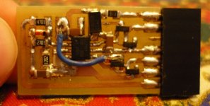
Nigel, attached you will find my controller board. As you can see its pretty small, however I use a simple temperature controlled solder station (a cheap Solomon SL-10), and usually I only fry about 1 out 30 from SOIC (for TSSOP my statictics are not so good).
Do not use PDIP converters, it os no question why this ICs are made only in small SMD packages. At freqs over 100kHz layout is important.
Would you like to have the layout and schematic plan of my simplified controller board? I can send you if you'd like.
On what inuctors you tested you meter? Some meters work pretty bad on ferrites, however work well on low-freq inductors and transformers and iron-powder cores.
Nigel, look at the datasheet of your ferite cores, it says Al=5000nH for thed Ferroxcube ETD54 3C90 ungapped. So if you do the math: L=Al*turn^2=845uh ungapped. So I am sure there is some problem.
An ETD39 has an al about 2700nH ungapped, so 13 turns should get 456uH. I am do using an ETD39 for >1kW with 13 primary turns (working 100-300kHz freq range), and I do have 50uH total primary inductance but WITH "BIG" GAP. So this is why I thinking about your LC meter.
I also send you a scope picture of how the outputs should like. Here I am using a BJT MMBT3904/3906 pair to boost the output of the IRS27951, to drive FETs with high gate charge (this is only necessary over 1kW).
Attachments
You don't need a hot air gun to solder smd parts a simple tempretaure control iron is sufficient enough.
Indeed, I usually just use my Metcal, but for any thermally enhanced packages, like LEDs or SOIC/SSOP/MSOP with an exposed pad on the underside, one can't easily solder what's not accessible. If you're using SOIC parts you can drill a large enough hole under the device to give you enough access from the rear, to solder the pad to the reverse side copper, but with smaller parts, this isn't practical and here the heatgun with solder pasted works a treat.
As it stands though, the parts Nigel is using aren't thermally enhanced and I've never destroyed a SMD chip with too much heat or from ESD. I don't know how robust these chips from National are though, they could be prone to destruction.
As it stands though, the parts Nigel is using aren't thermally enhanced and I've never destroyed a SMD chip with too much heat or from ESD. I don't know how robust these chips from National are though, they could be prone to destruction.
It could be that it is my pcb at fault for the problems and some chips are working and others aren't.
I didn't use a star ground so noise will get into the timing circuit.
I did hack the pcb to get the VB loop in a star connection.
Once I get my heat gun I will try again to get the circuit working.
It could be that it is my pcb at fault for the problems and some chips are working and others aren't.
Again I can offer you to send my controller's PCB design. Its pretty easiy, does not use compontents smaller than 1206, so can be soldered by hand easily. Also its on a separate board, so you can check the controller working separately, which is pretty useful.
Do you need my PCB design?
- Status
- This old topic is closed. If you want to reopen this topic, contact a moderator using the "Report Post" button.
- Home
- Amplifiers
- Power Supplies
- IRS27951 / IRS27952