I reduced Rmin to 2k2 and it fires up every time now and holds 6 amps per rail.
The recommended value of 3k9 forced the 27951 to reset.
You should scope the lower FET gate, and tha half bridge output, to check for ZVS or ZCS switching.
Although there should be no connection between Rmin and the trigger of overcurrent at startup, if the soft-start is set right.
Although there should be no connection between Rmin and the trigger of overcurrent at startup, if the soft-start is set right.
I looked through the spread-sheet again and altering my transformer also altered the start components and I had missed that.
I fixed the start up components and the circuit powers up every time even with the spread-sheet specified Rmin value of 3k9.
|I have built up another pcb and sadly the 27952 cant have been soldered in right and it blew mosfets, zener and 27951.
I only had high Rdson mosfets so put those in and replaced zener and 27952.
The circuit powers up ok now so long as there is no load.
I have ordered some more low Rdson mosfets and will try them when they arrive.
With my next pcb revision I will make longer pads for the 27952 so it is easier to solder by hand.
Before I power up a new pcb I have to buzz out every 27952 pin for connection to the pcb and for shorts between adjacent pins. Its a real nuisance, why cant IRF supply DIP.
Although there should be no connection between Rmin and the trigger of overcurrent at startup, if the soft-start is set right.
Backing off Rmin was allowing it to power up because it drew less current as it was further away from resonance.
Fixing the power up components now makes Rmin the correct value.
You should scope the lower FET gate, and tha half bridge output, to check for ZVS or ZCS switching.
How do I know if there is ZCS or ZVS ?
How do I know if there is ZCS or ZVS ?
Previously I posted a simulation picture where there was inductive operation (possibility of ZVS) but the dead-time was to small to achieve complete ZVS:
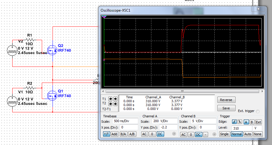
You can see in the red signal (lower FET gate) that there is miller plateau caused spike, the on the yellow signal (half bridge) that the transistion is very steep.
If you have capacitive mode (possibility of ZCS), then you will see the same, even if you have big time.
Even if you in capacitive mode that does not mean you can certainly achieve ZCS
") . (as if you in the inductive mode ZVS is a possibility with good dead-time)
. (as if you in the inductive mode ZVS is a possibility with good dead-time)Here is a very good link about ZCS resonant converters: http://schmidt-walter.eit.h-da.de/snt/snt_eng/snteng4b.pdf
If you in capacitive mode then the periodic time of your control signal must be longer then the resoant network periodic time. (FYI: IRS27951 is intended for ZVS resonant controller, it cannot be used as ZCS resonant converter controller)
Thanks for the explanation.
Things have fallen apart again. I blew up a set of mosfets, a 27952 and a zener diode.
I replaced them all but I am having trouble getting the 27952's soldered in again.
I have blown up two so I need to order some more. The blown 27952's power up in very odd modes, one mode has a very long HO with a very short LO. It should be a 50/50 pulse.
I have started work on a mark 2 pcb with much longer pads for the 27952, this means I can put solder on the pads and then run the soldering iron up to the pin taking the solder with it. This should put less stress on the 27952.
I also had trouble getting high power rectifier diodes and they were a silly price. I have replaced them with a 600 volt 10 amp bridge rectifier which is much cheaper.
You're welcomeThanks for the explanation.
Nigel, first practice soldering, I haven't blown up any SOIC case for about 3 years.I replaced them all but I am having trouble getting the 27952's soldered in again.
much longer pads for the 27952 .. This should put less stress on the 27952.
That is a good start. I alway use bigger pads than reccomended. This ease soledring, also bigger pads can dissipate more (so better thermal resistance.
I also had trouble getting high power rectifier diodes and they were a silly price. I have replaced them with a 600 volt 10 amp bridge rectifier which is much cheaper.
Where did you put those? On the secondary? Get them out ASAP!!!
For the secondaries you have two choices:
- ultrafast rectifiers (<100ns recovery time) for diodes >100V
- Schootky diodes (they have "no" recovery time) for diodes <200V
You CANNOT use normal slow (>1us) rectifiers! They will BLOW UP!
(i can buy MBR10100s for about 100ft (0,3 GBP))
You're welcome
Where did you put those? On the secondary? Get them out ASAP!!!
For the secondaries you have two choices:
- ultrafast rectifiers (<100ns recovery time) for diodes >100V
- Schootky diodes (they have "no" recovery time) for diodes <200V
You CANNOT use normal slow (>1us) rectifiers! They will BLOW UP!
(i can buy MBR10100s for about 100ft (0,3 GBP))
I put the bridge on the primary side.
I used ultra fast diodes for the secondary as it is over 100KHz.
I got some more 27952 through the post today.
I decided not to solder one in but use a zif socket into an 8 pin DIP on my pcb.
First of all it wouldn't work at all. I eventually found my zif socket is slightly too narrow and the 27952 wasn't seating properly.
Then it powered up but gave out the wrong waveform. This turned out to be my bench power supply not supplying enough current to run normally. This means I might have been throwing out perfectly good 27952's when they didn't power up properly after soldering in.
I think I will now wait until I get better pcb's through with larger pads on the 27952, this will allow pushing solder along the pad to the pin instead of heating up the 27952 at the pin. I suspect my soldering iron is far too hot for this. I have a large tip for soldering larger through hole components. I will see if I can find a smaller tip.
I think you have a good plan. First get a good PCB then a better soldering iron. I have one with a 0,8mm tip with temp control and of the 50+ SO chips none has failed sofar due to heating atleast.I solder pin by pin with fine.solder wire (high Q) no wick to remove excess solder and use extra liquid fluss , after I wash with isopropylalcohol.
Using a ZIF socket with these circuits doesnt sound right, will parasitic capacitance not affect.drive capacity etc, and general function.
But I encourage your courage to continue. Every morning I check this thread to follow your progress in the right direction!! Go go go!
thanks for sharing
Using a ZIF socket with these circuits doesnt sound right, will parasitic capacitance not affect.drive capacity etc, and general function.
But I encourage your courage to continue. Every morning I check this thread to follow your progress in the right direction!! Go go go!
thanks for sharing
It will take a couple of weeks for the new pcb's to come through.
Luckily I am always up for a challenge in electronics/software.
There have been a lot of mistakes but I am learning from them which was the object of the exercise.
You would probably laugh if I told you I had been in electronics for 30+ years.
Many times I was given things to do I hadn't done before but mostly came through with reasonable solutions in the end.
I have also bought an isolation transformer off ebay so I can look at the primary side and see what is going on. I have been working half blind up to now only seeing what was happening on the secondary side.
isolation tranformer
Hi Nigel,
I have my oscilloscope connected via an isolation transformer. The patient runs off mains.
I don't like that, when measuring - it's so dangerous.
When I had problems with the regulation loop, I wound me a special transformer with 10 times secondary and supplied the mains input of the SMPS from a Lab-supply. So I can safely measure.
Later I switched back to the 'right' transformer of course.
I decided to have a quick go at soldering in a 27952.
I soldered it in but got a blob of solder across two pins, so I wicked it off as quick as I could. I buzzed out the ic to look for shorts or open circuits and it was fine.
I powered it up off 30 volts but it was totally dead.
I had a dig around in my junk room and found an old temperature controlled soldering station. I set the iron to be just hot enough to melt solder (about 3/4 heat setting). I soldered in another 27952 and got a blob across two pins again. I wicked off the blob. This time the 27952 powered up fine.
It looks like my usual soldering iron is simply far too hot for smd work.
I powered up my pcb off mains and the output looks fine.
Last edited:
It is not the heat but the time , because when the.solder starts to melt temperature stays constant until.all is melted, after which temperature.increases again. I have my soldering iron set to 390 C (leaded tin) and a tiny chisel tip.
of course if the ironhas high power and a largish tip the temperature plateu is reached and passed over quickly and temperature rise fast. hard.tell.
all I can saybis that I am very very happy with my Ersa Micro60 solder station.
Good luck to you, can we see some pics perhaps?
of course if the ironhas high power and a largish tip the temperature plateu is reached and passed over quickly and temperature rise fast. hard.tell.
all I can saybis that I am very very happy with my Ersa Micro60 solder station.
Good luck to you, can we see some pics perhaps?
The wire is a fix to a ground loop, not sure now if it is still needed but my new pcb sorts that out.
Still a couple of components sticking up for slight changes and testing.
Still a couple of components sticking up for slight changes and testing.
An externally hosted image should be here but it was not working when we last tested it.
For some reason the 27952 blew up tonight during testing. I was taking quite a few amps when it stopped working.
Soldered in a new chip and of course that didnt work either.
So using liquid flux I soldered in another 27952 and that worked fine.
The flux seems to stop the solder blobbing so much and seemed to make things solder quicker.
Soldered in a new chip and of course that didnt work either.
So using liquid flux I soldered in another 27952 and that worked fine.
The flux seems to stop the solder blobbing so much and seemed to make things solder quicker.
- Status
- This old topic is closed. If you want to reopen this topic, contact a moderator using the "Report Post" button.
- Home
- Amplifiers
- Power Supplies
- IRS27951 / IRS27952