I've had a few threads on this circuit already based on different aspects. One contributor suggested I make a new one solely about the choke loaded supply.
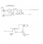
I'm including the schematic. The PSU output is 205VDC 12mA. This goes to the tube by way of output transformer. The only R/C is the tube bias.
Previously the prototype had this psu circuit with a regulated supply in front of it. The ripple was 45mV (.045vac) Now the ripple is 310mV (.31vac).
Someone modeled this in another thread and said it should be 37mV of ripple.
Both supplies show identical ripple. Each has its own separate ground plane.
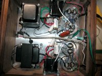
This is a two-box pre-amp, dual mono. Star grounded. Ground lift is a 100 Ohm/.22uF R/C which had the prototype dead quiet although that was on a single board with the rectified psu.
No scope here and while I try to find someone with a scope is there anything that looks off that I might explore? Sonically it sounds fine so fixing the ripple which will hopefully help expose a slight 60 cycle hum solution is all that's left.
I'm including the schematic. The PSU output is 205VDC 12mA. This goes to the tube by way of output transformer. The only R/C is the tube bias.
Previously the prototype had this psu circuit with a regulated supply in front of it. The ripple was 45mV (.045vac) Now the ripple is 310mV (.31vac).
Someone modeled this in another thread and said it should be 37mV of ripple.
Both supplies show identical ripple. Each has its own separate ground plane.
This is a two-box pre-amp, dual mono. Star grounded. Ground lift is a 100 Ohm/.22uF R/C which had the prototype dead quiet although that was on a single board with the rectified psu.
No scope here and while I try to find someone with a scope is there anything that looks off that I might explore? Sonically it sounds fine so fixing the ripple which will hopefully help expose a slight 60 cycle hum solution is all that's left.
Attachments
Last edited:
I am not an expert.
However, there are a couple of things I would tweak in PSUD2.
First, a 12mA Current Sync is usually more useful than a resistor as a load.
Second, you are using the default 2 ohms ESR on the caps. I would look it up on the spec sheet, or use .1 R. 2 R ESR caps are floor sweepings today.
Third, I would delay 10 sec to let the supply settle, then you can read the ripple off of PSUD2 directly.
HTH
Doug
310mV of ripple sounds much to me.
A supply I'm building right now shows 11mV(p-p) ripple in PSUD, using a B+ of 410V DC and a load current of 110mA. Filtering is LCLC using 5H, 120µF, 5H, 120µF.
With a 29H choke and 12mA load current I would expect less ripple...
Greetings,
Andreas
EDIT: As I am no tube expert, "much" is very much relative^^. Morgan Jones notes somewhere in one of his books that an upper limit of 5% of B+ would be a good design choice concerning ripple - that would be about 10V with your B+ of 200V....
Last edited:
Hi,
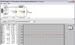
for the ripple, mark the checkbox for U(I1). This will show a graph of the voltage over current source I1, which is your load.
Zoom in (or out) as much as needed to see the minima and maxima of the (sinusoidal) voltage curve. Read out minimum and maximum B+ on the voltage scale --> ripple.
Greetings,
Andreas
Here is a suggestion of what I might do.
This has 26 mV of ripple, and has a reasonable Q.
Note that it doesn't overshoot when it starts up.
I just added a 200 ohm resistor to your choke.
You could add a larger cap for the same effect.
This example I upped C2 to 400 uF and was able to lower the resistance while eyeballing the Q.
The reason I use 1 inductor and one resistor is to prevent interactions (ringing) between the 2 filter sections.
HTH
Doug
Attachments
Thanks again. The rise time looks better. The choke is fixed at 200 Ohms. This program is giving me problems. Some times I can zoom in on the wave length and other times not.
Sorry to be so dim. Is the ripple the difference between min/max on voltage? Or is it already calculated somewhere.
Also what wattage do I need for the 200 Ohm resistor? 2W and above?
Sorry to be so dim. Is the ripple the difference between min/max on voltage? Or is it already calculated somewhere.
Also what wattage do I need for the 200 Ohm resistor? 2W and above?
Last edited:
Yes. Just add a resistor in series to form the composite part.The choke is fixed at 200 Ohms.
Choose a wattage that is 4 times larger than the power dropped. If you look at my first example for R1, the voltage is 2.6 V rms, from the last column, and 13 mA rms.
P = IV = .0338 Watts. I would still use a 2 Watt resistor.
I get ripple from the difference column. Look at the first example.Is the ripple the difference between min/max on voltage? Or is it already calculated somewhere.
You can use V(C3) or V(I1) and use the difference column. In this example its 27.354 mV. Note, I ran the simulation for 10 sec to stabilize the voltage. See the delay box to the right of the [Simulate] button. This does not work @ Time = 0 because the difference is the start = 0 V to the max voltage.
There was a Tutorial of PSUD2 in an online Issue Edited by one of the members here.
I will try to find it.
Doug
Thanks Doug. I need to step back and do some reading and learning. 27.354mV would be a great ripple target. At the moment with this psu circuit I'm getting 310mV of ripple which is completely unacceptable. Something must be injecting the AC into the circuit. What's odd is both mono channels have identical ripple readings above.
I just tried the 200 Ohms resistor. The ramp up has some spikes in it like the simulation. Clearly I have other issues because it had no affect on the 316mV of ripple. I even tried a 10H 200 Ohm choke there and again, no affect on the ripple. That has to be resolved before I can work with the PSU unfortunately.
If none of your changes to the filter chain has effect on the measured ripple, it is probably noise injected from somewhere - and the "real" power supply ripple is significantly lower so you don't see any changes.
I would start taking the whole thing to pieces and make a new test setup: transformer, rectification, filtering and a dummy load. Nothing else.
If the ripple is back to normal, add the rest of the circuit step by step until the problem reappears.
Greetings,
Andreas
I would start taking the whole thing to pieces and make a new test setup: transformer, rectification, filtering and a dummy load. Nothing else.
If the ripple is back to normal, add the rest of the circuit step by step until the problem reappears.
Greetings,
Andreas
These exercises prove your point. I figured it was being injected somewhere else. Its parasitic enough that its swapping any changes. Its interesting its being injected identically in both channels.
I'm thinking to pieces may be the only way to do it. I might have a lead on someone with a scope nearby. If it doesn't work out there's no other logical option I can see...
I'm thinking to pieces may be the only way to do it. I might have a lead on someone with a scope nearby. If it doesn't work out there's no other logical option I can see...
Measure twice. Cut once.
In this case it should read, "Measure the transformer CTs if you're not sure".
My transfo builder added an additional tap in case I wanted to raise the ground with voltage. There was some confusion and I kept getting the impression B+ CT was the red/yellow
Like an IDIOT I did not measure to confirm.
Do we see where this is going? That was the problem. It was the red/white.
With the proper CT the ripple at output went from 4mV to .48mV. The AC on the power caps went from 316mV to 48mV.
I have two options to get it down further. My choice would be add a choke between the output power caps say 10H.
At this point the hum isn't audible but would like to pursue reducing it more.
Thanks to everyone for all their help!
- Status
- This old topic is closed. If you want to reopen this topic, contact a moderator using the "Report Post" button.
- Home
- Amplifiers
- Power Supplies
- Any experts in choke loaded tube rectified power supplies?