Unfortunately I already have bought the caps based on my initial "dumb" sim, so will go ahead and build with 10,000 - 3r3 - 4,700 - 3r3 - 4,700... As I said an excercise in overkill!
Another observation I had when doing the sims (after realising the in-out difference needed to be 5V at least) was that it was better to have slightly lower resistance between the caps and higher ripple before the reg, if it meant that the pre-reg voltage was 5V or more higher, once the magic 5V was hit, any additional voltage (pre reg) made no difference... Of course this gets tricky as voltage drop increases as load current increases, so you need to choose the resistor values based on the max current draw expected.
Tony, what is your transformer's secondary and what is your intended load (voltage, min-max amperage)?
I may be able to set-up a mock-up of it, measure and see how it compares to your simulation results (in an attempt to fight the "overkill" approach
 ).
).Regards
George
Last edited:
abraxalito:
Are you measuring resistance or total impedance (which includes leakage inductance)?
What do you mean by "proximity effect"? Do you mean mutual inductance i.e. transformer action?
egberttheone:
The inductance of a wire-wound is unlikely to be sufficient to make much difference within the audio range.
A general comment on regulators. These are essentially a servo system (i.e. using negative feedback), so like all such systems they need to reduce their HF open-loop gain to avoid instability. This means that regulation falls off at higher frequencies, and the output impedance may become reactive. This means that you can't necessarily simply slap a big capacitor on the output to compensate, as it might make things worse. The datasheet will give guidance. Also, their internal gain may depend on 'supply voltage' which could be the difference between input and output. This explains the better behaviour with a bigger voltage drop.
Hi George,
I've pretty much decided to build as is only components I haven't purchased are the transformer and the RC resistors. I don't have anything else to use the caps for so don't want to waste them
I can't find my notes, but from memory estimated current draw was about 160mA per rail (it will be a dual rail + 0 - supply) planned transformer is a dual secondary torroidal 15V 30VA (once again probably overkill but I wanted a safety margin). I'm allowing for 200mA / rail as a possibility and more if I should decide to go with a completely different approach should my active crossover circuit be a flop. I do plan on building this soon! Just have to stop procrastinating and order the last remaining bits.
DF96, I also wasn't sure about the 1000uF on the output of the reg in my circuit since 100uF is about the biggest you seen in examples in the datasheets, It was something that Fred DieckMann had recommended the circuit is based on his Idea (and also something I've seen a number of people say on various sites was a good value for LM317's (provided there is enough ESR, which I am adding in the form of a low value resistor). Certainly the datasheet doesn't mention any problem with larger valued caps.
I figured it works in the sim so should be ok... if not I'll drop it back to 100uF or so.
BTW the overkill doesn't stop there, but once I build everything, if it works I'll post it This is certainly a "project by a fanatic"
Tony.
I've pretty much decided to build as is
only components I haven't purchased are the transformer and the RC resistors. I don't have anything else to use the caps for so don't want to waste them I can't find my notes, but from memory estimated current draw was about 160mA per rail (it will be a dual rail + 0 - supply) planned transformer is a dual secondary torroidal 15V 30VA (once again probably overkill but I wanted a safety margin). I'm allowing for 200mA / rail as a possibility and more if I should decide to go with a completely different approach should my active crossover circuit be a flop. I do plan on building this soon! Just have to stop procrastinating and order the last remaining bits.
DF96, I also wasn't sure about the 1000uF on the output of the reg in my circuit since 100uF is about the biggest you seen in examples in the datasheets, It was something that Fred DieckMann had recommended the circuit is based on his Idea (and also something I've seen a number of people say on various sites was a good value for LM317's (provided there is enough ESR, which I am adding in the form of a low value resistor). Certainly the datasheet doesn't mention any problem with larger valued caps.
Although the LM117 is stable with no output capacitors, like
any feedback circuit, certain values of external capacitance
can cause excessive ringing. This occurs with values between
500 pF and 5000 pF. A 1 μF solid tantalum (or 25 μF
aluminum electrolytic) on the output swamps this effect and
insures stability. Any increase of the load capacitance larger
than 10 μF will merely improve the loop stability and output
impedance.
I figured it works in the sim so should be ok... if not I'll drop it back to 100uF or so.
BTW the overkill doesn't stop there, but once I build everything, if it works I'll post it
This is certainly a "project by a fanatic" Tony.
Are you measuring resistance or total impedance (which includes leakage inductance)?
Just the resistance. My meter separates out the leakage inductance (around 4mH I think it was) on another display.
What do you mean by "proximity effect"? Do you mean mutual inductance i.e. transformer action?
No - the close relative of skin effect.
Proximity effect (electromagnetism) - Wikipedia, the free encyclopedia
Originally posted by egberttheone
First of all nice work.
You say you use wire-wound resistors, do you have a LCR meter to check the how much inductance these resistors have? This inductance could possible be helping to effectively smooth en the higher frequencies.
Originally posted by DF96
The inductance of a wire-wound is unlikely to be sufficient to make much difference within the audio range.
I measured 10 of them in series and divided the result by 10.
Then measured each one, and took the arithmetic mean .
Then added the result of these two operations and devided by 2.
The final value is L=12uH for each 4.7R/5W wire wound ceramic encapsulated resistor.
(Individual resistor’s inductances measured from 9 to 17uH on the 200uH range of my LC meter)
On the internet, I didn’t find any inductance value for such resistors.
So, I turned to the Ham world for coil calculations.
This site has more than I would like to know.
RF Inductance Calculator - HAMwaves.com
I broke the ceramic housing and measured the dimentions of one of the coiled resistors:
Coil’s Diameter: 3.7mm
Coil’s Length: 7.0mm
Wire’s diameter: 0.02mm
Number of turns: 12
Calculated L=0.3uH due to geometry, independent of frequency.
The frequency dependent Inductance is up to 500MHz another 0.3uH, so the total calculated L= 0.6uH.
Why such a big difference btn measured and calculated?
Probably due to the end cups and leads which are magnetic?
So, taking the highest inductance of the two (L=12uH) what can the HF roll-off be?
Here I give up.
Pi sections, T sections and the like, anyone?
Regards
George
Hi George,
I've pretty much decided to build as is only components I haven't purchased are the transformer and the RC resistors. I don't have anything else to use the caps for so don't want to waste them
Tony, I would place one of the largest capacitors just before the voltage regulator.
At least consider to leave enough space there for the big one to experiment with this later
.Regards
George
It seems that some regulators are OK with big caps, but object to small ones. As always, read the datsheet and don't assume that other designers have done so.
I've read it (actually TI's Natsemi's and LT's) multiple times
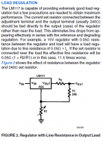
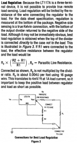
another thing which is not applicable to the 7818 but is a very important hint in the LM317A Data Sheet is that the top resistor in the resistive divider should be connected directly to the case of the regulator, NOT to the load, and the bottom resistor in the resistive divider should be connected with as low a resistance connection as possible directly to the load. Another example of why you SHOULD read the datasheet! You won't pick that up from any schematic In this case mutiple datasheets because they have subtly different information in them. first is from Natsemi, second from Linear Technology. Tony.
Attachments
Hi George, The layout is tight but I can see what I can do... Might breadboard it before putting it on the verro board! A breadboard is another thing in the shopping basket along with the resistors The 10,000uF caps are pretty big.... even 4700uF though should be more than enough don't you think I guess actual measurements will be the acid test.
Tony.
The 10,000uF caps are pretty big.... even 4700uF though should be more than enough don't you think I guess actual measurements will be the acid test.Tony.
I broke the ceramic housing and measured the dimentions of one of the coiled resistors:
Coil’s Diameter: 3.7mm
Coil’s Length: 7.0mm
Wire’s diameter: 0.02mm
Number of turns: 12
Calculated L=0.3uH due to geometry, independent of frequency.
The frequency dependent Inductance is up to 500MHz another 0.3uH, so the total calculated L= 0.6uH.
Why such a big difference btn measured and calculated?
Probably due to the end cups and leads which are magnetic?
Do you know the measurement frequency of your LC meter? It certainly could be that the end caps and steel leads are acting in some way like a high mu core for the coil, even though they're outside it. But the increase seems really dramatic.
So, taking the highest inductance of the two (L=12uH) what can the HF roll-off be?
Like DF96 says, not really significant in the audio band for a value of 12uH. The leakage inductance of your transformer will almost certainly swamp this by a few orders of magnitude (mine measured around 4mH). If it were a toroidal the leakage inductance would be lower but still considerably higher than 12uH. I think its safe to consider them just resistors in the present context.
Hi George, I've done some measurements using your technique. initial results posted here --> http://www.diyaudio.com/forums/power-supplies/188361-power-supply-questions-2.html#post2568395
Tony.
Tony.
- Status
- This old topic is closed. If you want to reopen this topic, contact a moderator using the "Report Post" button.
- Home
- Amplifiers
- Power Supplies
- PSU RC multistage filtering