Hi all
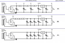
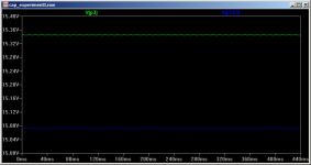
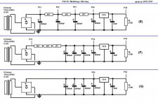
I did some ripple and noise measurements on 3 different versions of a simple 18Vdc PSU and I thought to share it with you.
The same materials were used on all three versions.
5W wirewound 4R7 resistors, 2W carbon 470R, and electrolytic caps.
AC Voltage measurements (through an 1uf MKT cap and a 47K carbon potentiometer to an M-Audio USB Audiophile sound card) were recorded as wav. files and then imported to RMAA 5.5 for spectrum analysis.
Attachments

Wow! From that article:
"The power then goes through ten cascaded RC stages of passive RC filtering..."
Massive indeed!
Wintermute: I would enjoy seeing the results with the cap order reversed too. I also used to think having the big one (usually one or more 10,000uF in my case) on the end of the chain was best to supply the load current between the 8.3mS chargings without having to pull it through the series resistor(s). But lately it does seem the opposite may be true. The waveshape seems a lot better (lower overall charging current peaks and more sinusoidal) having the big cap first.
Maybe best to think about the RC chain in terms of ripple reduction rather than supplying load current. The leftmost cap is hit with the highest level of ripple, of course (and should be rated for that). The ripple then decreases at each node to the right down the chain, presumably requiring smaller caps with lower ripple ratings (?).
Last edited:
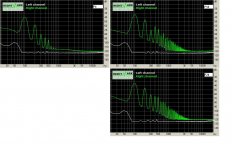
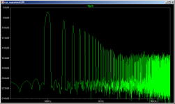
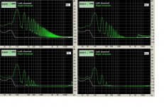
Something's not right here.
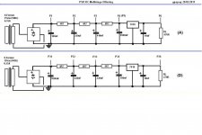
Circuits B and C have the same amount of capacitance (1760uF) after the rectifier but B has additional RC filtering action due to the 14.1 Ohms of resistance before the caps. The cutoff frequency of the RC filter in B is a low 6Hz.
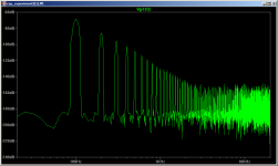
You would expect, therefore, the spectrum at P14 to have much lower HF content than that at P24, but they're almost identical. This cannot be correct.
Circuits B and C have the same amount of capacitance (1760uF) after the rectifier but B has additional RC filtering action due to the 14.1 Ohms of resistance before the caps. The cutoff frequency of the RC filter in B is a low 6Hz.
You would expect, therefore, the spectrum at P14 to have much lower HF content than that at P24, but they're almost identical. This cannot be correct.
P14 is a bit lower at HF than P24. Don't forget to include diode forward resistance and transformer resistance in the analysis, then the difference between B and C is small.
Comparing A with B reminds me of something I learnt in school chemistry about 40 years ago (when we were studying dilution). To get something clean, using a fixed amount of water (or other solvent), wash it lots of times using a small amount of water each time rather than one big wash using all the water. The same principle applies to RC smoothing.
Comparing A with B reminds me of something I learnt in school chemistry about 40 years ago (when we were studying dilution). To get something clean, using a fixed amount of water (or other solvent), wash it lots of times using a small amount of water each time rather than one big wash using all the water. The same principle applies to RC smoothing.
DF96 - you must have sharper eyesight than I do. I can't tell any difference worth mentioning.
Two diode drops should only be an ohm or so max, similarly the transformer resistance. With an additional 14 ohms of resistance in circuit B there should be a noticable reduction in the HF spikes compared to circuit C, especially beyond 1kHz, but I see none. If the Fc is 6Hz, they should drop off at 6dB per octave or 20dB per decade.
Two diode drops should only be an ohm or so max, similarly the transformer resistance. With an additional 14 ohms of resistance in circuit B there should be a noticable reduction in the HF spikes compared to circuit C, especially beyond 1kHz, but I see none. If the Fc is 6Hz, they should drop off at 6dB per octave or 20dB per decade.
Last edited:
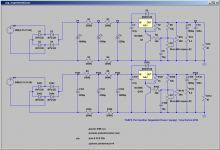
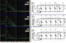
Hi agdr, I hadn't done any fft's of the sim but did so tonight. What I discovered is that the arrangement of caps with lowest to highest results in a lower voltage at the last cap than the other way around.
Originally when doing my sims (of LM317 reg) I didn't realise that I needed quite a bit higher than the dropout voltage in-out to get the best performance. The differences I saw were mainly due to the lower voltage more so than because of the difference in ripple pre-reg.
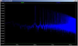
The results of the fft's is interesting. The noise floor (which is unrealistic anyway) is lower with the large cap first and I think the harmonics are slightly lower but the primary is exactly the same.
I'll post the various plots and the circuit diagram.
I've only shown the fft's at the point before the reg for each config and the comparison after the reg. Note that if I up the voltage pre rectifier the blue trace also goes down to -280db flat line, I know that this is completely unrealistic but it shows how even a small voltage difference before the reg can make a difference after!
The thing that surprised me the most was the voltage difference, it was something I didn't pick up before because I was looking at the post reg performance and basically ignoring what was happening before provided I had at least 3V higher than the output voltage. What I've since found was that at least 5V difference was necessary for best performance (at least with the model I have for the LM317).
Tony.
Originally when doing my sims (of LM317 reg) I didn't realise that I needed quite a bit higher than the dropout voltage in-out to get the best performance. The differences I saw were mainly due to the lower voltage more so than because of the difference in ripple pre-reg.
The results of the fft's is interesting. The noise floor (which is unrealistic anyway) is lower with the large cap first and I think the harmonics are slightly lower but the primary is exactly the same.
I'll post the various plots and the circuit diagram.
I've only shown the fft's at the point before the reg for each config and the comparison after the reg. Note that if I up the voltage pre rectifier the blue trace also goes down to -280db flat line, I know that this is completely unrealistic but it shows how even a small voltage difference before the reg can make a difference after!
The thing that surprised me the most was the voltage difference, it was something I didn't pick up before because I was looking at the post reg performance and basically ignoring what was happening before provided I had at least 3V higher than the output voltage. What I've since found was that at least 5V difference was necessary for best performance (at least with the model I have for the LM317).
Tony.
Attachments
Last edited:
Something's not right here.
Circuits B and C have the same amount of capacitance (1760uF) after the rectifier but B has additional RC filtering action due to the 14.1 Ohms of resistance before the caps. The cutoff frequency of the RC filter in B is a low 6Hz.
You would expect, therefore, the spectrum at P14 to have much lower HF content than that at P24, but they're almost identical. This cannot be correct.
Gopher thank you for commenting on it.
I was sceptical myself with the similarity of P14 Spectrum to the P24 Spectrum before I post them.
I had to retake both measurements, but the new measurement spectrums were the same as the old ones.
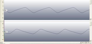
Then I looked at the wave files (all wave files are 10sec duration) from which these two spectrums were generated.
As you can see, they look quite the same. But the P24 waveform has sharper leading edge and smoother trailing edge compared to the P14 waveform.
I don’t know if this should translate to a different spectrum in theory.
Regards
George
Attachments
Hi George,
in the sims I've done having the bigger cap closest to the rectifier seemed to work best, could you reverse the order of the caps in A) and post the difference (if any)?
Tony.
Tony, here they are.
Thank you for the stimulus
") .
.By the way, what you wrote about the regulator OUT-IN voltage difference is spot on, as I found out these days that I am doing these measurements.
So much, that my measurements after the regulator (P6,P16, P26, P36) are to be taken with little credibility.
Some more measurements will follow
Regards
George
Attachments
The transformer is described as 15V, 0.15A. This is 2.25VA, which is a small transformer. Maybe this is just one secondary. Anyway, small transformers tend to have poor regulation. Let us assume 10% (20% might be more realistic, though). This means an effective secondary resistance of around 10 ohms, so the difference between B and C will not be huge - 7.6dB if other things are equal. Both should drop at 6dB/octave, but from different corner frequencies.
The plots show a much smaller difference than this, with some harmonics increasing! Maybe the OP can give us the figures, but my estimate from the plots is
100Hz 2dB
200Hz 1dB
300Hz -9dB
400Hz 3dB
500Hz 0dB
600Hz -5dB
700Hz 1dB
800Hz -10dB
900Hz 4dB
1kHz -7dB
The two plots show a very different harmonic structure, so comparison is difficult. I guess electrolytic ESR is a factor. Also, at the higher frequencies, details of grounding. Were the caps grounded exactly as shown - i.e. to a ground bus with the rectifier at one end and the regulator at the other?
PS the waveforms in post 11 suggest that the total resistance for B is about twice that for C, as the charging period takes about twice as long.
Last edited:
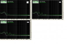
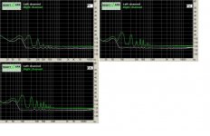
Hi,
your last set of results make perfect sense.
The multiple RC version delivers ~-13dB of 100Hz harmonic and ~-19dB of 200Hz.
The higher harmonics are down in the noise.
Then look back at the earlier postings and you will see this all falling into place.
I am surprised that the 7818 passes so much @ 50Hz. I think this indicates a layout problem. Charging circuit sharing routes with the regulator sense circuit??
Last edited:
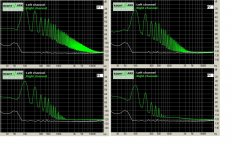
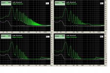
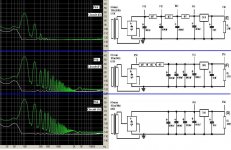
If I would mind gross differencies (which was my initial intention), I would make the following sum-up.
I check for better spectrum (that is, no high frequencies and low amplitude at low frequencies) at the input of the voltage regulator.
Thus I compare the three RC multistage circuits (A), (D), (E). See first attachment.
It is circuit (E). Quite obvious, as it has the largest total capacitance, thus largest RC constant. But for low power circuits, the cost and size penalties due to large capacitors are not great (*PS).
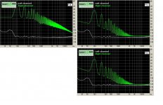
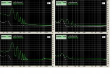
Then, I compare circuit (E) over (F) and (G), all having the same total capacitance. See second attachment.
It is circuit (E) again.
Regards
George
(*PS) If cost and size are a factor, then I would choose circuit (A) over circuit (D), as I think that (A) will behave better under dynamic conditions as well – changes of Rload – because the largest capacitor is closest to the changing load, with no resistor in between.
I check for better spectrum (that is, no high frequencies and low amplitude at low frequencies) at the input of the voltage regulator.
Thus I compare the three RC multistage circuits (A), (D), (E). See first attachment.
It is circuit (E). Quite obvious, as it has the largest total capacitance, thus largest RC constant. But for low power circuits, the cost and size penalties due to large capacitors are not great (*PS).
Then, I compare circuit (E) over (F) and (G), all having the same total capacitance. See second attachment.
It is circuit (E) again.
Regards
George
(*PS) If cost and size are a factor, then I would choose circuit (A) over circuit (D), as I think that (A) will behave better under dynamic conditions as well – changes of Rload – because the largest capacitor is closest to the changing load, with no resistor in between.
Attachments
Thanks George! good to see that what I am seeing in the sims translates into similar results in real tests. The result with the four 1000uF caps shows that brute force does work
That is what I was doing with my Sim, Finding what amount of capacitance I needed to use to get effectively no ripple on the output of the reg... It is an excercise in overkill and goes somewhat against the "conventional" logic of using a small amount of capacitance pre regulator and let the reg do the job of smoothing the output.
My original sim I did something dumb, and was halving my capacitance so was using double the sizes I actually needed. but when I re-ran the sim I did find that dropping the initial 10,000uF down to 4700uF did result in more ripple on the output... however there may have been a subtle drop in pre-reg voltage which gave me this result. I'll have to re-visit the sims with reduced capacitance keeping an eye on the input voltage and see if the results are any different. The main idea was to find the point where diminishing returns were making the expense of additional capacitance un-worthwhile.. Unfortunately I already have bought the caps based on my initial "dumb" sim, so will go ahead and build with 10,000 - 3r3 - 4,700 - 3r3 - 4,700... As I said an excercise in overkill!
Another observation I had when doing the sims (after realising the in-out difference needed to be 5V at least) was that it was better to have slightly lower resistance between the caps and higher ripple before the reg, if it meant that the pre-reg voltage was 5V or more higher, once the magic 5V was hit, any additional voltage (pre reg) made no difference... Of course this gets tricky as voltage drop increases as load current increases, so you need to choose the resistor values based on the max current draw expected.
Tony.
The transformer is described as 15V, 0.15A. This is 2.25VA, which is a small transformer. Maybe this is just one secondary. Anyway, small transformers tend to have poor regulation. Let us assume 10% (20% might be more realistic, though). This means an effective secondary resistance of around 10 ohms, so the difference between B and C will not be huge - 7.6dB if other things are equal.
Just mention here something I recently discovered about transformers. The resistance at DC is way lower than the AC resistance. With my LCR bridge measuring losses, I see a considerably higher value at 50Hz compared with what my multimeter shows me (the DC value). I think this is down to two factors - core losses and proximity effect.
Ah thanks for jogging my memory SY No, first off I didn't. Then I later realised my error - it certainly does reduce the reading considerably. I'll do it again and get back to you.
<edit> Shorting the primary when measuring the secondary means the flux is much reduced, so the core losses go down considerably. What I don't know is how this affects the proximity effect.
No, first off I didn't. Then I later realised my error - it certainly does reduce the reading considerably. I'll do it again and get back to you.<edit> Shorting the primary when measuring the secondary means the flux is much reduced, so the core losses go down considerably. What I don't know is how this affects the proximity effect.
Last edited:
- Status
- This old topic is closed. If you want to reopen this topic, contact a moderator using the "Report Post" button.
- Home
- Amplifiers
- Power Supplies
- PSU RC multistage filtering