
I made this charger,used ferrit transformer,BDX34 darlington,1k resistor and 22n capacitor.
And I want to enhance it. I doesn't work below 5V, I'd like to make it on 1,5V. What should I change?
Also I'd like to make this adjustable power with pot,but in pulse with modulation fashion,not just amplitude scaling. I don't want to use IC's, want to keep it simple.
Also I used transformer that can give 40-50W on 40-50kHz, but when I start it I have impression that it pumps less than 15W as it is now.
Designing a proper converter is a bit more complicated than throwing three components around any transformer.
You need to calculate the core area, number of turns, airgap, etc.
Self-oscillating converters look simple, but they are the most challenging to design.
And a fluorescent tube is a pretty challenging load too.
You should have a look at some application notes:
http://www.diodes.com/_files/products_appnote_pdfs/zetex/an1.pdf
http://www.diodes.com/_files/products_appnote_pdfs/zetex/an14.pdf
http://www.diodes.com/_files/products_appnote_pdfs/zetex/an17.pdf
If you want dimming, you'll need a Royer converter associated with a PWM controller
Thanks for links and references.
I've noticed that impedance of secundar is also important for neon to light properly.
Neon lamp does practically short circuit and that affects oscillating,it just pumps spikes with no energy. All that suggests to use 555 square generator, but then voltage supply should be at least 5V which I don't like.
Also I don't like transformer squealing, don't know how to make it silent?
I definitely want to use one transistor solution,no push pull.
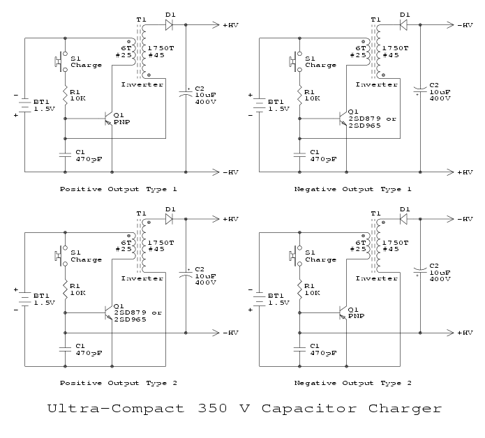
Here are some circuits for flash capacitator charging,they work on 1.5V.I'm confused how secundar of 350V is connected to transistor base?
I've noticed that impedance of secundar is also important for neon to light properly.
Neon lamp does practically short circuit and that affects oscillating,it just pumps spikes with no energy. All that suggests to use 555 square generator, but then voltage supply should be at least 5V which I don't like.
Also I don't like transformer squealing, don't know how to make it silent?
I definitely want to use one transistor solution,no push pull.
Here are some circuits for flash capacitator charging,they work on 1.5V.I'm confused how secundar of 350V is connected to transistor base?
I made this Royer variation,and it works very nice,only problem it has it works just with 10V or more. How to bias it to work at least voltage possible (3V for example)?
I used BDX34 for Q1,Q2.
I used BDX34 for Q1,Q2.
An externally hosted image should be here but it was not working when we last tested it.
Using the main winding also as the feedback one is a bit borderline. But since you want to work at low voltages, this shouldn't be an obstacle.
But why do you insist on using BDX34's?
These are darlingtons, pretty unsuitable for this kind of application.
You should use Zetex superbeta transistors (ZTX849, etc), they are ideal for this kind of job. Or alternatively, a D44H11 or similar.
To make the circuit operate at low voltages, you'll also need to reduce R1 & R2; to 820ohm f.e.
Yes, but I don't like that extra winding for feedback, it's hard to control frequency and power with such design.
I made R1, R2 1k,and it's oscillating on 3V but doesn't have voltage to fire the lamp. Don't know how to solve that? I have 2 x 3 rounds on primary and approximatively 1 x 500 on secondary.
Also discovered that L1 and C1 affect oscillating allot. If I haven't need low (3V) operating voltage I'd just use CD4047 to drive transistors (MOSFET's).
Last edited:
It is the opposite: having a separate winding increases flexibilityYes, but I don't like that extra winding for feedback, it's hard to control frequency and power with such design.
Using proper transistors, you could get ~1500V peak at the output. With the BDX34's, this will fall to ~1000V, which is insufficient to trigger the tube without preheating. Did you make heating connections?I made R1, R2 1k,and it's oscillating on 3V but doesn't have voltage to fire the lamp. Don't know how to solve that? I have 2 x 3 rounds on primary and approximatively 1 x 500 on secondary.
That's normal, this kind of oscillator has to be tuned.Also discovered that L1 and C1 affect oscillating allot.
Edit: I found it,it's 3 turns.
I made it oscillating, but still it wont start lamp. It looks like I don't have enough turns in secondary, but I have bad experience when you start it without load it just cut through isolation and short-circuits it.
Ill try some faster transistors like BUxxx and see if it will glow on 3V.
I made it oscillating, but still it wont start lamp. It looks like I don't have enough turns in secondary, but I have bad experience when you start it without load it just cut through isolation and short-circuits it.
Ill try some faster transistors like BUxxx and see if it will glow on 3V.
The Zetex circuit works perfectly, even with BD131 transistors.
The output voltage is 800V peak, which is probably insufficient for most tubes, but you can increase the number of secondary turns to 700 f.e. (you have to use a proper ballast capacitor in series).
Did you implement a correct airgap? Did you use the right value for C3?
The output voltage is 800V peak, which is probably insufficient for most tubes, but you can increase the number of secondary turns to 700 f.e. (you have to use a proper ballast capacitor in series).
Did you implement a correct airgap? Did you use the right value for C3?
Attachments
TUbe driver
Hi vasko
elvee is right, Royer converters can run from 3V. I published a 6V, hot-cathode tube driver based on this (using Zetex transistors) in EPE magazine March 2008 which you could use as the basis for your design. It's not easy to upgrade this to 40W. Running at 12V will draw 3.5A or so and ifyou resonate the primary you will need very high current capacitors, or two 2A types in parallel. If you resonate the secondary the current burden is lower but you still need a capacitor with high dV/dt rating.
If you are using a hot cathode FT then use a separate starting arrangement (preheat).
FOr CCFL you need kV's - even more dangerous! Also, high voltage windings have to be done with care - as you found they can break if the insulation /winding is not right. I only managed it winding thin wire in individual layers with insulated (waxed) paper like the old days, not "piled" as most coils are currently.
cheers
John
I made new transformer. Secondary with ~2500 turns now. Now it glows on 1.5V battery.
But there is not much power. I guess that on ~50 kHz transformer that size could give 30-40W instead 1.5A that I have on 3V now.
It seems like you can't have both. Safe start and power.
I suggested a 40% increase in the number of turns, you went for a five-fold increase!.
Sure, it will strike any tube at any supply voltage, but the current will be reduced in the same proportions.
You have to be reasonable, choose a number of turns that will comfortably trigger your tube, even at a reduced power supply, and then select a secondary ballast capacitor to adjust the power level.
And good, high current transistors like the ZTX are a must if you want high power at low voltages.
SIMetrix now has a transformer model which you can select some pre-defined ferrite cores or put in manual data for core size. YOu can account for an air gap by changing the effective permeability.
But to choose the core size, check the size of wire needed for the current, etc, you may have to use standard transformer equations!
cheers
John
But to choose the core size, check the size of wire needed for the current, etc, you may have to use standard transformer equations!
cheers
John
I published a 6V, hot-cathode tube driver based on this (using Zetex transistors) in EPE magazine March 2008
can someone give me link of this article?
- Status
- This old topic is closed. If you want to reopen this topic, contact a moderator using the "Report Post" button.
- Home
- Amplifiers
- Power Supplies
- Neon lamp charger