Hi
Hi metalsculptor thanks for the reply. No worries. Well I've done a test with the unit with 220V and modified gate drive. At switch on, the transformer started to buzz and did so until the fuse blew up it lasted nearly a minute or so, before the fuse was blown(less brutally than before). Could it be core saturation? Do you think there is a way to test magnetizing current at low voltages ~60V to debug this issue?
Hi metalsculptor thanks for the reply. No worries. Well I've done a test with the unit with 220V and modified gate drive. At switch on, the transformer started to buzz and did so until the fuse blew up it lasted nearly a minute or so, before the fuse was blown(less brutally than before). Could it be core saturation? Do you think there is a way to test magnetizing current at low voltages ~60V to debug this issue?
It does sound a bit like saturation but that could be a symptom of bad drive as well.
To test for saturation, some means to monitor the current in the transformer primary is needed, the small current transformer that a lot of computer SMPS's have should do for that purpose. You also need a means to slowly increase the input voltage, a variac would be ideal because there might only be a 20V difference between normal running and saturation.
Increase the voltage while watching the magnetising current on the CRO, the current will get very spiky if the core starts to saturate.
Have you thought of using bootsrap hi side driver instead of a transformer coupled one?
Putting a 100W light in series with the power supply while testing at low load might prevent blowing up mosfets, the light will illuminate if there is a fault.
Thanks
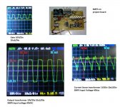
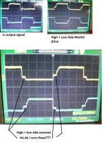
Hi metal sculptor. Sorry for late repaly i had problems with my pc. its fixed now. Attached you will see the waveforms. I still wish to go the transformer way but i wouldn't mind looking at a schematic of bootstrap drive which could be implemented as discrete or IR2110 if i am not wrong") . Thanks a lot for the advice about the bulb it might help i will implement it. Its also used sometimes in amplifier testing. You will see the current waveform in the attachment i would greatly appreciate your advice about the waveforms. By the way the gate drive looks exactly the same for hi and lo side which is why i included only 1 pic. Thanks
. Thanks a lot for the advice about the bulb it might help i will implement it. Its also used sometimes in amplifier testing. You will see the current waveform in the attachment i would greatly appreciate your advice about the waveforms. By the way the gate drive looks exactly the same for hi and lo side which is why i included only 1 pic. Thanks
Hi metal sculptor. Sorry for late repaly i had problems with my pc. its fixed now. Attached you will see the waveforms. I still wish to go the transformer way but i wouldn't mind looking at a schematic of bootstrap drive which could be implemented as discrete or IR2110 if i am not wrong
. Thanks a lot for the advice about the bulb it might help i will implement it. Its also used sometimes in amplifier testing. You will see the current waveform in the attachment i would greatly appreciate your advice about the waveforms. By the way the gate drive looks exactly the same for hi and lo side which is why i included only 1 pic. ThanksAttachments
GDT
Gate drive signal is very good, but at low input 40V?
in the other picture it looks not so good
Is that circuit connected to the 220VAC line?
It looks bad, Be carefull
Show more pictures, bigger ones.
Hi metal sculptor. Sorry for late repaly i had problems with my pc. its fixed now. Attached you will see the waveforms. I still wish to go the transformer way but i wouldn't mind looking at a schematic of bootstrap drive which could be implemented as discrete or IR2110 if i am not wrong
Gate drive signal is very good, but at low input 40V?
in the other picture it looks not so good
Is that circuit connected to the 220VAC line?
It looks bad, Be carefull
Show more pictures, bigger ones.
Thanks for the reply
Hi autoclassA thanks for the reply. To which waveform are you referring the current sense or the main transformer waveform? I feel more the current sense . Do you have any suggestion of the problems which could be causing the current sense waveform to be like this? The current sense is measured across a current sense transformer in series with the main transformer. The circuit is blowing fuse and mosfet at 220V which is why i am testing and debugging the circuit at low voltage ac before goign higher.Thanks for your help
Hi autoclassA thanks for the reply. To which waveform are you referring the current sense or the main transformer waveform? I feel more the current sense . Do you have any suggestion of the problems which could be causing the current sense waveform to be like this? The current sense is measured across a current sense transformer in series with the main transformer. The circuit is blowing fuse and mosfet at 220V which is why i am testing and debugging the circuit at low voltage ac before goign higher.Thanks for your help
Gate waveform issues
Hi i managed to get a proper DSO and the gate waveforms are looking like attached as well as the latest schematic. Is there anyway that this sginal can be improved to overcome to remove the step in the signal? Thanks
Hi i managed to get a proper DSO and the gate waveforms are looking like attached as well as the latest schematic. Is there anyway that this sginal can be improved to overcome to remove the step in the signal? Thanks
Attachments
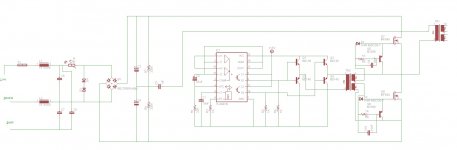
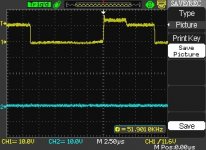
Is there a voltage drop on your 15V source? perhaps your drawing too much current from the +15V. The delay from of the voltage drop could be caused when your cap C2 depletes. Add +15V to your scope on the second probe to see if matches the Vgs voltage drop.
If thats not try looking connecting TR2 Input to the probe to see if there is a voltage drop. Perhaps the TR2 Transformer is saturating. Which Vgs: HighSide, LowSide or Both has the voltage drop?
While testing at a higher voltage, try using smaller half-bridge capacitor (C5). That would limit the input current per switching cycle. Its possible at the higher voltage you have a ringing issue with inductance leakage. I don't see any Snubbers\clamps on your circuit and you don't have any gate resistors either. Gate Resistors are used to help remove oscillation caused by ringing. Just use something small like 8 or 4 ohms for gate resistors.
Its also possible that a leakage spike is exceeding the breakdown voltage of 500V. Rectifed 220AC is 310VDC. even a small inductance leakage could top 500V. I didn't see an waveform for the Transformer input for voltage spikes or diode ringing. Post that.
Alternatively you could replace the Gate Transformer with a half-bridge MOSFET driver.
Hi techguy thansk for the reply regarding your points:
1) I will check that Vdrop but i know what could be causing it nothing alarming.
2) What would be the signs of T2 saturating? I have a normal voltage on the GDt when loaded
3) Yes Gate resistors are being implemented
4) Smaller C5 what value would you suggest, 50% or 25% of its actual value? And how much would it help in preventing my mosfet from burining?
5) Effectively no snubbers on TR1 - main core i need to get eberything back to one piece and i will post the waveform output. Your explanation about leakage inductance seems 100% plausible in my case. Let me complete with what am going through and we can get to it.
Thanks
Hi techguy thansk for the reply regarding your points:
Smaller C5 what value would you suggest, 50% or 25% of its actual value? And how much would it help in preventing my mosfet from burining?
Thanks
Start with something tiny, perhaps 250-500 pf, just enough so you can run your circuit and take a look at the waveforms. The smaller the cap, the lower the current will be passed per each switching cycle. Generally when I test a new circuit I use a tiny cap, just to see if there is something wrong. Sometimes its a bad solder connection, or an under\oversize resistor causing the problem. starting off with a small switching cap is a lot cheaper than a blow mosfet.
I suspect that adding snubbers will address the issue of the blow Mosfet, but test using a tiny switching cap to confirm.
Hi Techguy thanks for the reply i will try to get 500pF 1KV Cap for the test. Another thing that's bugging me. The AL for my gate transfo is 800 i have read that advised AL for aget drive at least toroids have an AL of >3000. Do you have anything you can share about this? Thanks
- Status
- This old topic is closed. If you want to reopen this topic, contact a moderator using the "Report Post" button.
- Home
- Amplifiers
- Power Supplies
- GDT loading Question