I was wondering if anybody tried or thought about the idea of using a cheap SMPS compared to mains frequency transformer to get the voltage required, then use a linear regulator to clean up the noise?
Did a few simple sims and it seems pretty easy to get ripple and noise down to way below 10mV even with the worst of power supplies, regulation's pretty good too.
Efficiency's low, wide input voltage range and PFC, and little efficiency penalty if the output also needs to be adjustable using the SMPS to drop most of the voltage. With cost slightly higher than the SMPS alone and noise level somewhere between linear and switching, how sweet is that?
Last edited:
set your ripple target much lower than 10mVac, or is that 10mVpp?.....................easy to get ripple and noise down to way below 10mV even with the worst of power supplies, regulation's pretty good too.
....................Efficiency's low,
There is no need for low efficiency.
With a fixed input voltage from the smps and a fixed output voltage from the linear then the voltage overhead of passing through the linear can be trimmed very low to maintain good output impedance for all likely current loadings.
That was a very conservative estimate. I randomly threw together some values with the worst SMPS that could ever exist and what I got:
Think there's much room for improvement still. I'm green at this so it would really help if I could be given some pointers on how to choose the values.
An externally hosted image should be here but it was not working when we last tested it.
Think there's much room for improvement still. I'm green at this so it would really help if I could be given some pointers on how to choose the values.
Last edited:
If you can spare the voltage overhead, a little RC ahead of the regulator helps a lot in stopping HF switching noise passing straight through the reg (which has very little gain at HF)
Example:
Using 3-pin regulators off-piste: part 2
Example:
Using 3-pin regulators off-piste: part 2
Last edited:
Thanks for your reply. At first I did an RC with some values but for a 6A load the C had to be too large. But decided to try it again after reading your reply. Settled for 0.1ohm 2200uF for 2A load, HF greatly reduced and ripple is below 300uVp-p.
This will do for now while I search for the appropriate component models.
Thanks AndrewT too for telling me to set my target much lower.
This will do for now while I search for the appropriate component models.
Thanks AndrewT too for telling me to set my target much lower.
Hi,
I´d not opt for an 3-pin Reg but a simple gyrator circuit instead, because of bandwidth issues. It needs to be effective in filtering out HF. Ripple rejection can be made high enough too, because the ripple frequency is high and the filtering Gate/Base- RC-circuit doesn´t need a low value of the R.
jauu
Calvin
Take a look at the schematic in the link at the bottom of that good page martin clark provided the link to:
Hear it in the one drop
The gyrator kills much of the wideband smps noise, then following it with your LT1083 can provide some regulation. You wouldn't use the follow-on op amp error amp, of course, with your amperage needs.
Hear it in the one drop
The gyrator kills much of the wideband smps noise, then following it with your LT1083 can provide some regulation. You wouldn't use the follow-on op amp error amp, of course, with your amperage needs.
Last edited:
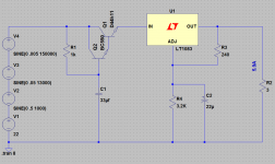
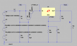
Maybe something like this, for 18V 6A, using your voltage sources. Fc = 4.8Hz (1k and 33uF) from that article.
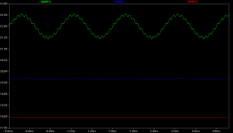
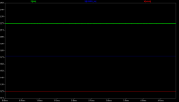
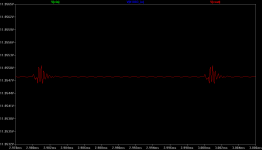
Green = Q1 collector
Blue = LT1083 in
Red = LT1083 out
Green = Q1 collector
Blue = LT1083 in
Red = LT1083 out
Attachments
Last edited:
Hi,
even bad SMPS feature quite high clock-frequencies (>>10kHz). So a simulation should be done at more realistic ripple-freqs.
If You add a parallel resistor to C1 in post #9, the gyrator features voltage regulation too. The output will be the resistor-divider´s -2x Ube.
Add a electrolytic/ceramic cap combination from Q1s emitter to gnd to cope with the loads current demands.
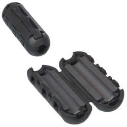
Optionally a ferrite bead ahead of the gyrator may impove matters also.
Imho this is sufficient for audio supplies and You can safely omit with the series regulator, without loss of performance.
jauu
Calvin
even bad SMPS feature quite high clock-frequencies (>>10kHz). So a simulation should be done at more realistic ripple-freqs.
If You add a parallel resistor to C1 in post #9, the gyrator features voltage regulation too. The output will be the resistor-divider´s -2x Ube.
Add a electrolytic/ceramic cap combination from Q1s emitter to gnd to cope with the loads current demands.
Optionally a ferrite bead ahead of the gyrator may impove matters also.
Imho this is sufficient for audio supplies and You can safely omit with the series regulator, without loss of performance.
jauu
Calvin
Would it be easier if I used AC analysis instead?
(the 1.75k resistor should've been 2.4k)
I think I'll settle for the third one since I already ordered the parts for the top right for a small 3-5A~ish amp. But the gyrator will be very useful when I want to power a computer.
So glad I made this thread! Learnt a lot of things!
An externally hosted image should be here but it was not working when we last tested it.
An externally hosted image should be here but it was not working when we last tested it.
An externally hosted image should be here but it was not working when we last tested it.
An externally hosted image should be here but it was not working when we last tested it.
(the 1.75k resistor should've been 2.4k)
I think I'll settle for the third one since I already ordered the parts for the top right for a small 3-5A~ish amp. But the gyrator will be very useful when I want to power a computer.
So glad I made this thread! Learnt a lot of things!
Last edited:
I like Calvin's idea of the ferrite bead ahead of the gyrator! Seems like that or a choke would go along way to nailing the switching spike in particular. The article in martin clark's post mentioned maybe using 20 turns of magnet wire around a resistor for an input choke.
Here is the same circuit but with a 6mA load instead of 6A. Note the (regulated) output is still the same, but look where the gyrator output voltage is at now.
That's without the resistor Calvin mentioned though. That is a great suggestion he has. It might be enough regulation for what you are doing and would avoid the added regulator drop. Or, conversely, add Calvin's resistor and then feed that to the regulator. Might be even flatter.
Attachments
Last edited:
Thanks, Calvin!
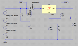
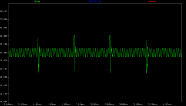
So, maybe something like this, now 12V out at 4A load.
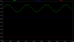
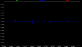
I've adjusted the voltage sources to more-or-less produce the scope waveform from the laptop power brick in that article. A 30mV p-p switching spike at a 50kHz rate, plus the scope seems to show 1 mHz background noise from somewhere, if I'm reading the divisions correctly.
Going from 4A to 4mA load the output of the gyrator now only goes from 17.2V to 18V with that parallel resistor added to C1.
So, maybe something like this, now 12V out at 4A load.
I've adjusted the voltage sources to more-or-less produce the scope waveform from the laptop power brick in that article. A 30mV p-p switching spike at a 50kHz rate, plus the scope seems to show 1 mHz background noise from somewhere, if I'm reading the divisions correctly.
Going from 4A to 4mA load the output of the gyrator now only goes from 17.2V to 18V with that parallel resistor added to C1.
Attachments
Last edited:
Hi AndrewT,
Good question! I would have expected the ferrite bead to do more (in terms of supression). I probably have the value too low - 10uH (?) I'm most likely doing something wrong with the model there. I found this:
Ferrite Beads
"Ferrite beads are often used in gigahertz filtering applications. Ferrite beads come in two flavors: high-Q, resonant beads and low-Q, nonresonant beads, also called lossy, or absorptive beads. The high-Q type has no place in a digital circuit. These beads are used to construct RF oscillators and filters and other circuits that need highly resonant circuit elements. In a digital power-filtering application, the last thing you want is resonance. The low-Q type is commonly used for power-supply filtering, in series with the power connection. Most often, this style of filter also has a capacitor to ground on either side of the inductor (Figure 1)."
I'm pretty out of date - my last 15 years have all been finance and operations. I'm still a coil guy with not a lot of knowledge about ferrites. Hopefully someone will post a better model for wwenze to try. I'm probably going to build one myself for fun. A laptop brick - to - audio-worthy supply filter would be a handy thing to have. I'm going to go crawl back under my rock for now, lol.
Good question! I would have expected the ferrite bead to do more (in terms of supression). I probably have the value too low - 10uH (?) I'm most likely doing something wrong with the model there. I found this:
Ferrite Beads
"Ferrite beads are often used in gigahertz filtering applications. Ferrite beads come in two flavors: high-Q, resonant beads and low-Q, nonresonant beads, also called lossy, or absorptive beads. The high-Q type has no place in a digital circuit. These beads are used to construct RF oscillators and filters and other circuits that need highly resonant circuit elements. In a digital power-filtering application, the last thing you want is resonance. The low-Q type is commonly used for power-supply filtering, in series with the power connection. Most often, this style of filter also has a capacitor to ground on either side of the inductor (Figure 1)."
I'm pretty out of date - my last 15 years have all been finance and operations. I'm still a coil guy with not a lot of knowledge about ferrites.
Hopefully someone will post a better model for wwenze to try. I'm probably going to build one myself for fun. A laptop brick - to - audio-worthy supply filter would be a handy thing to have. I'm going to go crawl back under my rock for now, lol.
Last edited:
When it comes to SMPS regulation, it may turn out easier to regulate the dropout voltage between linear reg's output and input to th whole linear stage.
Typical smps regulation voltage to ground measurement can become problematic when you think about dropout margin, tolerance, parameters wander etc. while not sacrificing efficiency too much.
Typical smps regulation voltage to ground measurement can become problematic when you think about dropout margin, tolerance, parameters wander etc. while not sacrificing efficiency too much.
forget the ferrite bead.I probably have the value too low - 10uH (?)
Look at your capacitance multiplier.
Some of your capacitance multipliers have omitted the necessary lower resistor. They cannot work properly.
None of your capacitance multipliers have a two stage RCRC holding the base at a ripple free voltage.
Sort the capacitance multiplier, to give a very low ripple at the input to the regulator.
Then the regulator only has to cope with meeting the variable demand of the load, without having to (poorly) attenuate input interference.
- Status
- This old topic is closed. If you want to reopen this topic, contact a moderator using the "Report Post" button.
- Home
- Amplifiers
- Power Supplies
- Linear post regulator for SMPS, what's your take?