Forget the ringing, look at the circuit, filter capacitor on the audio side, leakage inductance on the transformer side, what is the impedance of the filter capacitor at the ringing frequency vs the impedance of the leakage inductance and stray capacitance?
Hundreds of kilohertz at a volt or so supplied by a source with an inductance of millhenries looking into the largest bypass capacitor in the entire amplifier. I fail to see how this noise is going anywhere provided the low level signals are not run near the transformer side of the filter capacitors. Show me the ringing on the PSU rails and It might be of concern.
Hundreds of kilohertz at a volt or so supplied by a source with an inductance of millhenries looking into the largest bypass capacitor in the entire amplifier. I fail to see how this noise is going anywhere provided the low level signals are not run near the transformer side of the filter capacitors. Show me the ringing on the PSU rails and It might be of concern.
Hi,
I've been designing a new stereo chipamp with integrated PSU on the same PCB. As I got into details with the design, a kind of interesting topic came up regarding PSU. I want to keep it simple, but good. As I read (quite a lot) on this topic, the following became interesting for me:
1) Schottky rectifier diodes: many DIYers affirmed, that using schottkys improves sound quality
2) There were discussions about the puffer capacitors: to use huge (1 .. 2 x 10000uF) or small (1 .. 2 x 1000uF) capacitors. Some said, that lower capacitance improves sound quality, but of course degrades bass performance in case of high listening levels.
3) Type of reservoir capacitors also seems having effect on the sound. One complained, that he tried to use low ESR PSU capacitors, to keep PSU impedance as low as possible. This PSU resulted his worst sounding amplifier ever.
4) Type of transformer seems also have an effect: however we could say, that this component should not have an effect on sound quality (if voltage and power requirements are met), but it seems it has. It's not the same if a low or a (too) high powered xformer is used, or if it is an EI type
5) Putting low value capacitors (let's say 10nF) parallel with rectifier diodes are said to eliminate 'switching noise' of diodes.
6) Some are adding serial (!!!) 0.1 .. 0.5 Ohm resistors after rectifier diodes, before reservoir capacitors
7) Some tried snubber networks on the PSU rails, and reported improved sound.
I think it's not possible that so many DIYers are wrong, and they tricky solutions don't produce any improvement in sound. So I tried to find a theory, or lets say possible explanation to all of points mentioned above. By the way, 7th one does not really fit in the picture.
What if the main reason of 'disturbance' in sound quality is always the same, and these solutions above are just trying to attenuate this disturbance, but then don't exactly eliminate the root cause. What I have is only a theory, not proven by any measurement, only simulations are performed.
So the theory:
It is usually not considered, but transformers are not ideal: they have leakage inductance on secondary side (with primary winding shortened, or driven by an ideal voltage source). This inductance can be (I suppose) 1mH. Reason is the not 100% coupling between primary and secondary. There's an other thing which is even more rarely considered: transformers have own capacitance. I assume this capacitance in in the 1nF range somewhere. A transformer as-it-is is a huge tank circuit. When current flows thru it, and this current is cut off, it starts ringing at a high frequency determined by inductance and capacitance. (of course inductance of wiring, parasitic capacitance, and also junction capacitance of rectifiers, etc. should also be taken into account)
The higher the current flows on the tank circuit, the higher amplitude we have as a result, when current is cut off. The higher the inductance we have, the lower frequency and higher amplitude of ringing we have. The higher capacitance we have, the lower amplitude, and lower frequency ringing we get.
Once a high frequency ringing is present in the circuit, it's very likely that it causes problems in the audio band, because it's 'radiated' all over the circuitry.
Let's go back to the points above:
1) Schottky diodes have a less steep characteristic at low currents. So using Schottkies might reduce peak current on tank circuit, so ringing might be reduced
2) When large capacitors are used, currents are higher in the charging phase of capacitors. Using low capacitors might reduce peak current on tank circuit, so ringing might be reduced
3) Low ESR capacitors highly increase peak currents, they assist ringing of transformer
4) Different type of transformers have different leakage inductance and self capacitance. They might have a huge impact on ringing issue.
5) When capacitors are added parallel to diodes ringing frequency gets lower, so it's amplitude. But ringing is not totally eliminated!
6) Serial resistors also reduce charging current of capacitors, so current of tank circuit, that's why they reduce ringing.
7) Snubber networks do not eliminate effect described here. But a snubber on the reservoir capacitors can reduce coupling HF 'noise' to the amplifier's power lines
What could be a solution? A snubber. A snubber circuit connected to the transformer, and not to the rectified voltage.
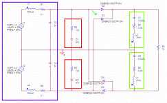
The schematic:
Blue: mains tr ansformer, with leakage inductance, self-capacitance and serial resistance included. Values are not real-life values, but might be close to that
Green: reservoir caacitor with ESR and ESL drawn. Values are close to real life.
Red: Snubber. It cannot really be designed correctly, because inductance and capacitance values of transformer are not known. 47nF and 100Ohm gave a good result for large variety of transformer inductance and capacitance.
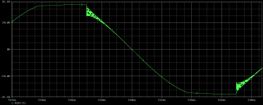
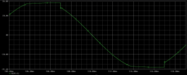
Screen-shots: Voltage on secondary of transformer, with and without snubbing.
I'm quite convinced that such a ringing is usually present in many PSUs. The question, if it's really degrading to the sound quality, and reducing ringing improves overall performance.
What do you think about all of these? Does it all make sense? Would someone try this out with real components?
Regards,
Peter
I've been designing a new stereo chipamp with integrated PSU on the same PCB. As I got into details with the design, a kind of interesting topic came up regarding PSU. I want to keep it simple, but good. As I read (quite a lot) on this topic, the following became interesting for me:
1) Schottky rectifier diodes: many DIYers affirmed, that using schottkys improves sound quality
2) There were discussions about the puffer capacitors: to use huge (1 .. 2 x 10000uF) or small (1 .. 2 x 1000uF) capacitors. Some said, that lower capacitance improves sound quality, but of course degrades bass performance in case of high listening levels.
3) Type of reservoir capacitors also seems having effect on the sound. One complained, that he tried to use low ESR PSU capacitors, to keep PSU impedance as low as possible. This PSU resulted his worst sounding amplifier ever.
4) Type of transformer seems also have an effect: however we could say, that this component should not have an effect on sound quality (if voltage and power requirements are met), but it seems it has. It's not the same if a low or a (too) high powered xformer is used, or if it is an EI type
5) Putting low value capacitors (let's say 10nF) parallel with rectifier diodes are said to eliminate 'switching noise' of diodes.
6) Some are adding serial (!!!) 0.1 .. 0.5 Ohm resistors after rectifier diodes, before reservoir capacitors
7) Some tried snubber networks on the PSU rails, and reported improved sound.
I think it's not possible that so many DIYers are wrong, and they tricky solutions don't produce any improvement in sound. So I tried to find a theory, or lets say possible explanation to all of points mentioned above. By the way, 7th one does not really fit in the picture.
What if the main reason of 'disturbance' in sound quality is always the same, and these solutions above are just trying to attenuate this disturbance, but then don't exactly eliminate the root cause. What I have is only a theory, not proven by any measurement, only simulations are performed.
So the theory:
It is usually not considered, but transformers are not ideal: they have leakage inductance on secondary side (with primary winding shortened, or driven by an ideal voltage source). This inductance can be (I suppose) 1mH. Reason is the not 100% coupling between primary and secondary. There's an other thing which is even more rarely considered: transformers have own capacitance. I assume this capacitance in in the 1nF range somewhere. A transformer as-it-is is a huge tank circuit. When current flows thru it, and this current is cut off, it starts ringing at a high frequency determined by inductance and capacitance. (of course inductance of wiring, parasitic capacitance, and also junction capacitance of rectifiers, etc. should also be taken into account)
The higher the current flows on the tank circuit, the higher amplitude we have as a result, when current is cut off. The higher the inductance we have, the lower frequency and higher amplitude of ringing we have. The higher capacitance we have, the lower amplitude, and lower frequency ringing we get.
Once a high frequency ringing is present in the circuit, it's very likely that it causes problems in the audio band, because it's 'radiated' all over the circuitry.
Let's go back to the points above:
1) Schottky diodes have a less steep characteristic at low currents. So using Schottkies might reduce peak current on tank circuit, so ringing might be reduced
2) When large capacitors are used, currents are higher in the charging phase of capacitors. Using low capacitors might reduce peak current on tank circuit, so ringing might be reduced
3) Low ESR capacitors highly increase peak currents, they assist ringing of transformer
4) Different type of transformers have different leakage inductance and self capacitance. They might have a huge impact on ringing issue.
5) When capacitors are added parallel to diodes ringing frequency gets lower, so it's amplitude. But ringing is not totally eliminated!
6) Serial resistors also reduce charging current of capacitors, so current of tank circuit, that's why they reduce ringing.
7) Snubber networks do not eliminate effect described here. But a snubber on the reservoir capacitors can reduce coupling HF 'noise' to the amplifier's power lines
What could be a solution? A snubber. A snubber circuit connected to the transformer, and not to the rectified voltage.
The schematic:
Blue: mains tr ansformer, with leakage inductance, self-capacitance and serial resistance included. Values are not real-life values, but might be close to that
Green: reservoir caacitor with ESR and ESL drawn. Values are close to real life.
Red: Snubber. It cannot really be designed correctly, because inductance and capacitance values of transformer are not known. 47nF and 100Ohm gave a good result for large variety of transformer inductance and capacitance.
Screen-shots: Voltage on secondary of transformer, with and without snubbing.
I'm quite convinced that such a ringing is usually present in many PSUs. The question, if it's really degrading to the sound quality, and reducing ringing improves overall performance.
What do you think about all of these? Does it all make sense? Would someone try this out with real components?
Regards,
Peter
Attachments
Last edited:
")
What's the effect of changing the frequency of V1 and V2 from 1 kHz to that of full wave rectified mains (i.e. 100 Hz or 120 Hz)?
The Bode plotter sweeps the circuit from an "initial" to a "final" value. So while 1kHz is specified in the "voltage component" description, it is actually "swept" from 10kHz to 50 MHz.
I fail to see how this noise is going anywhere provided the low level signals are not run near the transformer side of the filter capacitors. Show me the ringing on the PSU rails and It might be of concern.
I think the idea is three-fold:
1. The ringing is present on both the secondary of the transformer as well as the primary. If present on the primary, you have some noise that is inserted into the entire 120V distribution.
2. The ringing is present to an extent on the raw DC bus. For those using passive RC or LC filtering for say DHT's, you are presenting the cathode with this noise, which IS audible by experience. If using regulation with say a LM317, you still have to cope with the effective attenuation vs frequency of the linear regulator. It may or may not be effective depending on the application.
3. The noise is radiated throughout the chassis, preferring the high source impedance high gain signal circuitry. Since this is also occurring twice each cycle, you have 120Hz beats pulsing this noise. Rather than attempting exotic shielding or layout techniques to try and prevent picking up any noise, it is much easier to snub it at the source.
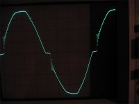
Screen shot of a simple rectifier transformer, using schottky's to feed a DC bus. I could see this noise at the heater pins of the triodes, post-regulator.
Attachments
The noise is radiated throughout the chassis, preferring the high source impedance high gain signal circuitry.
I second that. I had a pretty good sounding integrated amp from a well respected local manufacturer that was very quiet with my old ca. 90dB sensitive speakers. The amp is well laid out, with mu metal shielded toroid and shielded signal cable inside. Still, when I moved to speakers with ca 104dB sensitivity it was suddenly too noisy, with the PS switching noise being dominant. It is a very characteristic buzzing, and I am pretty convinced that it contributed to a slight harshness that the setup had.
Even if you may not hear switching noise under all circumstances I do not understand why you would NOT want to take the small extra effort to minimise it.
Good, it will filter the noise that it is carried over the rails itself - if it is properly dimensioned and has a high enough resonant point, but you still have the radiated noise inside the chassis. Besides, the inductor plus the snubbers will be more effective still.An inductor.
Last edited:
Hi,
My experience with snubbers is within Switch Mode Power Supplies, but I believe that even at 60Hz the diode current turn-off may be abrupt enough to excite some ringing.
A few issues are that the frequency can be quite high and able to radiate and couple into sensitive areas, another is that this ringing can be a determinant to diodes reliability.
A technique for snubbing this ringing is to put a critical value R across the device and a dc blocking capacitor to eliminate the dc current thru the R (and hence power dissipation).
So I carefully measure the ringing period and then add capacitance until the frequency has halved (or at least until I can see that the added capacitance is now dominating).
If you halve the frequency then you now have x4 as much capacitance in the resonant LC. Use this info to calculate the circuit C (1/4 the added C if you halved the frequency) then calculate the impedance of the original circuit capacitance at the original resonant frequency and use the same value Resistor.
Then you'll have a well dampened RLC circuit with the added R in series with a just large enough blocking cap (too big and the power dissipation goes way up).
You shouldnt have to go much larger than a hundred pf's when trying to effect the ringing frequency.
Again I'd have to look but I doubt the AC rectifiers are anywhere close to the problem presented in the switchers.
Hope this helps
-Antonio
Good, it will filter the noise that it is carried over the rails itself - if it is properly dimensioned and has a high enough resonant point, but you still have the radiated noise inside the chassis. Besides, the inductor plus the snubbers will be more effective still.
Even if it is little, it will filter the HF rubbish still. If it is properly dimensioned it will regulate the voltage very nicely.
Of course it has to be shielded, or put in a separate box psu. Choke input psus are not for the faint of heart.
I see snubbers mostly across rectifiers to block their RF noise, rather than the mains one.
Not that other RC filters cant be put in the psu, but an effective way is like this:
AC-xcapacitor-trafo-rectifiers-snubbers-L-C-RCC
Where in the last part there can be a capacitance multiplier, and 2 bypasses.
I think the idea is three-fold:
1. The ringing is present on both the secondary of the transformer as well as the primary. If present on the primary, you have some noise that is inserted into the entire 120V distribution.
2. The ringing is present to an extent on the raw DC bus. For those using passive RC or LC filtering for say DHT's, you are presenting the cathode with this noise, which IS audible by experience. If using regulation with say a LM317, you still have to cope with the effective attenuation vs frequency of the linear regulator. It may or may not be effective depending on the application.
3. The noise is radiated throughout the chassis, preferring the high source impedance high gain signal circuitry. Since this is also occurring twice each cycle, you have 120Hz beats pulsing this noise. Rather than attempting exotic shielding or layout techniques to try and prevent picking up any noise, it is much easier to snub it at the source.
Screen shot of a simple rectifier transformer, using schottky's to feed a DC bus. I could see this noise at the heater pins of the triodes, post-regulator.
Thanks for the detailed reply, I see where you are coming from. I never considered putting noise back into the mains much of a problem because it is noisy anyway and PSU's are very effective at removing mains noise but it could make the effect of ground loops more severe.
I can see the problem with directly heated cathodes if the heaters are supplied from the HT transformer, the LM317 doesn't have a high frequency response so it passes it. I have always considered powering heaters from the HT transformer poor practice. Have you tried fast soft recovery diodes?
The noise shouldn't radiate though the whole chassis, I assume that your chassis has a metal partition around the PSU components with a screwed on bottom which also screws into the partition. This is construction typical of valve era instrumentation and communication equipment. If so then the PSU noise circulates within the box containing it. That is why switchmode PSU's are boxed.
As for mu metal shielded toroids, there is no point if the current carrying leads are widely spaced and free to radiate everywhere, far better to box the entire power supply. Even twisting the leads to the rectifier and filter capacitors will help
This has made me curious so I will measure the rails of my next power supply, I don't expect any radiated noise because I am putting it in a 2mm thick steel box and the standard mains noise filter should keep any HF noise from going back into the mains.
- Status
- This old topic is closed. If you want to reopen this topic, contact a moderator using the "Report Post" button.
- Home
- Amplifiers
- Power Supplies
- Snubbing or not