Im making a PSU PCB with onboard rectifiers.
Im a little unsure as to what I should do to improve it, not that I dont know about snubbers etc, but Im not sure they they make a real world difference.
Read the snubber pdf from hagerman and it looks like snubbing does work. However, does that carry over to real world differences? Sure, anyone can come in here and write that they hear a difference, but do they really hear a difference or do they THINK they hear one?
Are there any measurably diffrences on the output of an amplifier depending on whether the PSU is snubbed or not?
Attachments
")
I've been thinking about using snubbers for the rectifier in a PS. Are there any typical values for the cap-resistor combination? Or do I have to derive them each time based on data specific to my PS?
What is standard? Are you aware that they actually have little packaged "snubbers" RC units, a resistor and capacitor together in one package? I have a few of them in my parts bin. .1uf+330 ohms and .22uf+330 ohms.
I was under the impression that if you used fast recovery diodes or Schottky diodes etc, that you wont really need snubbers, but what do I know.
By standard I meant ballpark values. After reading the hageman article it seems like there is a need to measure circuit inductance and capacitance to optimize the design. This is why I asked if there are any standard values for maybe a pass amp PS.
Anyway, I'll ceck out the single package part. I was not aware that these things existed.
Anyway, I'll ceck out the single package part. I was not aware that these things existed.
Snubbers should reduce hf noise from the rectification. I would use them even WITH Shottky diodes.
Nice the single package ones. I'll get em next tine.
Where is the high frequency noise coming from? Not from the rectifiers if you are rectifying at AC line frequency, here in the U.S. it is 60Hz.
60Hz is not high frequency! If noise is getting in through the AC line, then maybe you should consider an AC line filter before the power supply.
from the switching noise of the rectifier diodes. Diodes make noise when they change state between conduction and off. Shottkys produce less, but it is still there. This is a large problem in SMPS because of the higher switching frequency but it is still present in 60Hz rectifiers, though not as significant. It is also helpful to place a small film cap, 1uf or so, in paralell with the electrolytic filter caps to help filter and source current to the load for the higher frequecies.
Last edited:
the noise comes from the tank circuit formed by the leakage inductance of the transformer, the junction capacitance of the diode (changes with voltage) and parasitic capacitance and inductance -- for torroid transformers the leakage inductance is low, so the frequency is pretty high. I've used EI transformers from HP amplifiers and the leakage inductance can be in the milli-Henries which will put the resonant frequency into the audio band.
Question please, anyone.
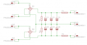
I noticed in the picture (schematic) of the power supply that it uses two bridge rectifiers. What is the difference or advantage when using two bridge rectifiers as opposed to one?
Thank you
Im making a PSU PCB with onboard rectifiers.
I noticed in the picture (schematic) of the power supply that it uses two bridge rectifiers. What is the difference or advantage when using two bridge rectifiers as opposed to one?
Thank you
Attachments

Last edited:
I would say yes, but. . . .
How do you know it is having the desired effect if any effect at all unless you can measure the noise/ripple?
So, without measuring these unknowns, can snubbers be implemented?
How do you know it is having the desired effect if any effect at all unless you can measure the noise/ripple?
from the switching noise of the rectifier diodes. Diodes make noise when they change state between conduction and off. Shottkys produce less, but it is still there.
Exactly.
It is also helpful to place a small film cap, 1uf or so, in paralell with the electrolytic filter caps to help filter and source current to the load for the higher frequecies.
Even better two a bigger and a smaller film to avoid resonances, like 47uF and 0,1uF.
the noise comes from the tank circuit formed by the leakage inductance of the transformer...
There are many source of noises...
There are many source of noises...
The noise we are talking about is that arising from the switching action of the diode -- if you;ve a scope with a delayed trigger you can see it and measure the frequency.
Let's take for example a 2x42V 500VA toroid from Antek. Leakage inductance measured on a GR 1658 was about 580uH. If you're using MUR860 diodes, the junction capacitance is around 80pF -- the frequency at which the tank resonates is 1/f=2PI SQRT (LC) =~ 740kHz
Values are R=2.7k, C=500pF per Hagerman "Calculating Optimum Snubbers".
Here's a Bode plot of before and after:
Attachments
The noise we are talking about is that arising from the switching action of the diode -- if you;ve a scope with a delayed trigger you can see it and measure the frequency.
Let's take for example a 2x42V 500VA toroid from Antek. Leakage inductance measured on a GR 1658 was about 580uH. If you're using MUR860 diodes, the junction capacitance is around 80pF -- the frequency at which the tank resonates is 1/f=2PI SQRT (LC) =~ 740kHz
Values are R=2.7k, C=500pF per Hagerman "Calculating Optimum Snubbers".
Here's a Bode plot of before and after:
What's the effect of changing the frequency of V1 and V2 from 1 kHz to that of full wave rectified mains (i.e. 100 Hz or 120 Hz)?
- Status
- This old topic is closed. If you want to reopen this topic, contact a moderator using the "Report Post" button.
- Home
- Amplifiers
- Power Supplies
- Snubbing or not