Hi,
Once again, I turn to the wisdom of the forum to seek advice..
I have buildt a pair of amplifier chassis with 3 separate amplifier channels each for stereo with 3-way active x-over.
My challenge is how to manage grounding and avoid ground loops when I hook the three amps up to an internal x-over card..
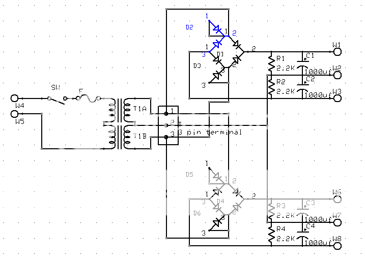
As you can see, I have enclosed a simple schematic.
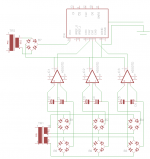
The Supply consists of one Toroid with dual secondary windings, feeding three separate pairs of rectifiers.
Each of these recctifier pairs feed a separate bank of capacitors, one for each amplifier channel.
The thought behind this was to isolate the power supply for each amp channel, so that the current draw in one channel would have a minimum effect on another channel.
I used some random op-amp symbols to illustrate the amplifiers.
On the schematic, you will allso see a integrated circuit, which is supposed to illustrate the 3-way active x-over. This x-over is fed from a separate low-voltage winding frrom the toroid through a regulated supply (only rectifier shown)
The signal ground for both input and outputs for the x-over is common and connected to the 0V of the X-over power supply.
The input RCA ground is connected to the chassis.
The only other thing connected to the chassis is the mains safety ground.
So here's the problem:
When hooking up only one amplifier to an output of the x-over, everything is fine.
Hooking up two amplifiers to the x-over creates a lot of hum on the output of both those amplifier channels.
Obviously some sort of ground loop.
The solution that seems most likely, is to connect the 0V points in the amplifier power-supply together as a star point as they are now effectively 3 "floating" 0V points.
I checked the voltage between two of these 0v points, and there was a potential of about 100 mV across.
Is it safe to connect the 3 0V points in the power-supply?
Can it give rise to any other issues?
Will it solve my problem?
Are there any other workable solutions??
I hope I have described the problem at hand in a way that makes sense, and that some of you find my problem worthy your time and consideration, and any input will of course be greatly appreciated.
Best regards,
Elbert
Once again, I turn to the wisdom of the forum to seek advice..
I have buildt a pair of amplifier chassis with 3 separate amplifier channels each for stereo with 3-way active x-over.
My challenge is how to manage grounding and avoid ground loops when I hook the three amps up to an internal x-over card..
As you can see, I have enclosed a simple schematic.
The Supply consists of one Toroid with dual secondary windings, feeding three separate pairs of rectifiers.
Each of these recctifier pairs feed a separate bank of capacitors, one for each amplifier channel.
The thought behind this was to isolate the power supply for each amp channel, so that the current draw in one channel would have a minimum effect on another channel.
I used some random op-amp symbols to illustrate the amplifiers.
On the schematic, you will allso see a integrated circuit, which is supposed to illustrate the 3-way active x-over. This x-over is fed from a separate low-voltage winding frrom the toroid through a regulated supply (only rectifier shown)
The signal ground for both input and outputs for the x-over is common and connected to the 0V of the X-over power supply.
The input RCA ground is connected to the chassis.
The only other thing connected to the chassis is the mains safety ground.
So here's the problem:
When hooking up only one amplifier to an output of the x-over, everything is fine.
Hooking up two amplifiers to the x-over creates a lot of hum on the output of both those amplifier channels.
Obviously some sort of ground loop.
The solution that seems most likely, is to connect the 0V points in the amplifier power-supply together as a star point as they are now effectively 3 "floating" 0V points.
I checked the voltage between two of these 0v points, and there was a potential of about 100 mV across.
Is it safe to connect the 3 0V points in the power-supply?
Can it give rise to any other issues?
Will it solve my problem?
Are there any other workable solutions??
I hope I have described the problem at hand in a way that makes sense, and that some of you find my problem worthy your time and consideration, and any input will of course be greatly appreciated.
Best regards,
Elbert
Attachments
Last edited:
Personally I think I single bridge per channel with the Zero Volts coming from the transformer windings would be safest. That is how I did the powersupply for my Gainclone which has a single traffo, and separate rectifiction and cap bank for each channel. I don't know whether it will be safe to connect zero volts points together with your setup, as you might run into problems with differences in the diodes, not all conducting/rectifiying equally. (note that is just a suspicion, not based on any practical or theoretical knowledge, someone else would be better to answer with respect to your actual implementation I'm just relating what worked for me ") ).
).
I don't think adding a third channel would matter. The above is absolutely dead quiet.
Mine was all done on a single PCB as it was a low capacitance supply, zero volts point is a bolt in the middle of the PCB, Bottom lead goes back to the traffo terminal block, each channels speaker ground , followed by each channels power grounds and then finally signal grounds.
Tony.
Last edited:
Hi thinking about this some more (your schematic makes my head hurt ) I'm a bit confused as to how your input wiring is organised.... The choice of symbols in your schematic could be better I think
if there is more than one path from your main input to the crossover through to the speaker output of the amps then you may have a problem there.. How have you got your speaker outputs 0V wired, are they completely separate to each "floating" point in the power supply?
Tony.
) I'm a bit confused as to how your input wiring is organised.... The choice of symbols in your schematic could be better I think if there is more than one path from your main input to the crossover through to the speaker output of the amps then you may have a problem there.. How have you got your speaker outputs 0V wired, are they completely separate to each "floating" point in the power supply?
Tony.
I guess I could have done well enough with the conventional single rectifier per channel.
I just figured that a double set of rectifiers would be a more conservative design in terms of halving rectifier load, and according to some texts I've read, such a dual rectifier approach allso keeps the transformer wires completely separated from what's going on on the DC side.
Your point about diode diferences etc, is interresting, this could perhaps explain why I measured a difference of 0,1V between two of the power supply floating grounds.
I apologise for the schematic, Windows 7 doesn't like my old scanner, I could not do a sketch and post it, so I had to improvise with a layout program in stead.
The speakers are wired to 0V from their respective amplifier cards.
In my initial post, I mentioned ground-loop, but as far as I can see from my schematic, I have no ground loop.
On the other hand, whenever there is a voltage potential between any of the power supply floating 0V points, current will flow between these 0V points, and as the layout is now, the only way is through the signal ground connections to the X-over.
The more I think about it, the more convinced I get that I 'll have to tie together the three 0V points in the power supply as a star point, run a separate ground-wire from that point to the X-over, and make sure signal wires screens are only grounded in one end to avoid loops.
Hmm.. Am I on the right track here, or have I overlooked something??
Hi Elbert,
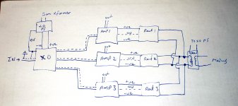
I drew up what I think it your schematic so that I could try and trace the ground paths.. If I've drawn it correctly all of the zero volts points on the amps should be connected (via the signal grounds) back to the 0V on your crossover power supply.. You haven't given details as to how that power-supply's zero volts is derived..
The only path I can see for the ground loop is via the rectifiers between amp channels. I think if you tied the zero volts together at the amps it would actually make the situation worse (unless as you say you only connect one end of the signal shields).
You could try running wires from your zero volt points on the amps back to your star point (0V point on your crossover PSU) and only run the signal wire (no shield) to each amp. Although as you say perhaps locally connecting them all and then running a single wire back to your crossovers zero volts star point would be better as there will not be a chance for resistance differences between the paths back to the true zero volts point.
attached is the diagram I drew up.. note that I didn't draw the transformer properly (only one winding) to simplifiy the idea, it was more a block diagram to work out potential paths.. there would of course be two windings connection per rectifier block.
looking at this again, I would say that the zero volts from each rectifier should be connected to the zero volts point of the XO PS. and separate connections should be made from there to the XO and each AMP. (alternatively have a local star for the amp psu's which is connected back to the xover ps zero volts and each amp only connected to that local psu star with no other zero volts path back to the XO. Try to keep all connections as short as possible and the same length.
I hope someone else will chime in as I'm really not 100% certain about this.
Tony.
Attachments
Last edited:
Tony,
Your interpretation of my schematics seem to be spot on, well done! (must buy a working scanner soon..)
Regarding the 0 v of the x-over supply, its a bit of an odd one. I only had one low voltage winding available, but needed a +/-15V supply. One AC line is connected to the centre of a capacitor pair and the other AC line feeds two diodes of oposite direction which then alternately feeds the plus or the minus side of the capacitor pair. Following this "single-to dual supply converter" there is a pair of voltage regulators (LM series) and some more capacitors. And yes, it works very well!
So the ground of the X-over power supply is allso floating with no other connection to chassis, transformer center taps etc..
Yesterday, I jumped the gun and tied together all three 0V points in the power supply (on the capacitor banks). No smoke or other signs of impending doom!
I tried to hook up the X-over card in various ways. and with various ground-configurations, some according to your desccription. I was able to avoid any greal ground loops, but I did have some general hum and noise. I attribute this to the prototype connection of the cards which involves the odd un-shielded lab-wire etc..
When the X-over card is finished and installed in the chassis. I'll aim for one single ground connection to the X-over from the PSU star point, either through a separate ground cable or through the shield of just one of the signal connections betweenamp and X-over. I'll leave the shielding connected in one end only on the other cables to avoid loops.
Your interpretation of my schematics seem to be spot on, well done!
(must buy a working scanner soon..)Regarding the 0 v of the x-over supply, its a bit of an odd one. I only had one low voltage winding available, but needed a +/-15V supply. One AC line is connected to the centre of a capacitor pair and the other AC line feeds two diodes of oposite direction which then alternately feeds the plus or the minus side of the capacitor pair. Following this "single-to dual supply converter" there is a pair of voltage regulators (LM series) and some more capacitors. And yes, it works very well!
So the ground of the X-over power supply is allso floating with no other connection to chassis, transformer center taps etc..
Yesterday, I jumped the gun and tied together all three 0V points in the power supply (on the capacitor banks). No smoke or other signs of impending doom!
I tried to hook up the X-over card in various ways. and with various ground-configurations, some according to your desccription. I was able to avoid any greal ground loops, but I did have some general hum and noise. I attribute this to the prototype connection of the cards which involves the odd un-shielded lab-wire etc..
When the X-over card is finished and installed in the chassis. I'll aim for one single ground connection to the X-over from the PSU star point, either through a separate ground cable or through the shield of just one of the signal connections betweenamp and X-over. I'll leave the shielding connected in one end only on the other cables to avoid loops.
Hi Elbert, good to hear that you are making some progress
One suggestion I would try (and it goes against some of what you will read on grounding) is to not make the chassis connection from your signal ground, but to make it instead from your star point.
Another thing you can try is moving your transformer.... My integrated amp picks a LOT of noise from the toroid. Moving it outside the chassis pretty much eliminates a lot of hum and other undesirable noise.. it isn't excessive but it is noticable within about 1M of the speakers when nothing is playing. If moving it reduces the hum, then you can try rotating it or changing it's orientation.
Another thing, was this new hum with no inputs connected or with inputs connected? If with inputs connected do they also have 3 pin plugs (ie a safefty ground)? There could be a ground loop between equipment.
Tony.
Tony,
Sorry for my much delayed response here!
I've been quite absorbed lately with active x-over design, so the grounding problem has sort of come a bit in the bacground..
Anyway, your suggestion is very interresting, and when the time comes to install the x-over cards properly in the chassis with screened cables all the way, It is one I'll certainly give a try!
Regarding the transformer, I don't have much leeway in terms of placement, nor do I wish to remove it from the chassis alltogether..
Having said that, I don't think the transformers are a big problem with regards to hum.
Earlier on, whern I first tested the amplifier cards, I connected a loudspeaker directly to the card, thereby bypassing the output relays of the protection cards.
With the card signal input shorted to ground, I could hear a faint buz if i put my ear just over the speaker.
I then switched off the amp, but the amp kept running for some seconds due to the rather large power-supply capacitors, and the hum was still there!
From that, I concluded that the hum came from an external source and that it would hopefully be reduced when I installed the cover and front panel on the amp.
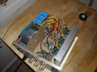
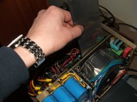
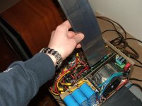
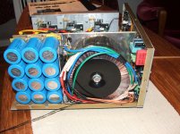
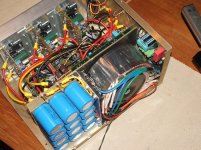
In the enclosed image, you can see the placement of the Toroid transformer.
Allthough my design is fairly compact, the transformer sits in a separate compartment.
In addition to that, I placed a sheet of permalloy mu-metal on the compartment wall behind the transformer. I allso wrapped a strip of the same material around the circumference of the Toroid. How much this actually helps, I do not know, I just decided to do it as a precaution.
Annyway, When the dau\y comes to hook everything up properly, I'll make sure to post the findings here!
Sorry for my much delayed response here!
I've been quite absorbed lately with active x-over design, so the grounding problem has sort of come a bit in the bacground..
Anyway, your suggestion is very interresting, and when the time comes to install the x-over cards properly in the chassis with screened cables all the way, It is one I'll certainly give a try!
Regarding the transformer, I don't have much leeway in terms of placement, nor do I wish to remove it from the chassis alltogether..
Having said that, I don't think the transformers are a big problem with regards to hum.
Earlier on, whern I first tested the amplifier cards, I connected a loudspeaker directly to the card, thereby bypassing the output relays of the protection cards.
With the card signal input shorted to ground, I could hear a faint buz if i put my ear just over the speaker.
I then switched off the amp, but the amp kept running for some seconds due to the rather large power-supply capacitors, and the hum was still there!
From that, I concluded that the hum came from an external source and that it would hopefully be reduced when I installed the cover and front panel on the amp.
In the enclosed image, you can see the placement of the Toroid transformer.
Allthough my design is fairly compact, the transformer sits in a separate compartment.
In addition to that, I placed a sheet of permalloy mu-metal on the compartment wall behind the transformer. I allso wrapped a strip of the same material around the circumference of the Toroid. How much this actually helps, I do not know, I just decided to do it as a precaution.
Annyway, When the dau\y comes to hook everything up properly, I'll make sure to post the findings here!
Attachments
Elbert,
If I'm not mistaken your bridge arrangement puts all the return side diodes (for each of the secondary windings) in parallel (they share a connection to the tx on one side and they share a common ground on the other). Though this will work the diodes wont share current evenly so make sure each is rated for the sum. This may also help in guiding you through your grounding paths.
Hope this helps
-Antonio
Earlier on, whern I first tested the amplifier cards, I connected a loudspeaker directly to the card, thereby bypassing the output relays of the protection cards.
With the card signal input shorted to ground, I could hear a faint buz if i put my ear just over the speaker.
I then switched off the amp, but the amp kept running for some seconds due to the rather large power-supply capacitors, and the hum was still there!
From that, I concluded that the hum came from an external source and that it would hopefully be reduced when I installed the cover and front panel on the amp.
I think that is a very valid conclusion!
so you may well be fine once all mounted in the proper chassis with all shielding in place! Probably a wise choice to be not chasing it any further at this stage. Tony.
After spending a lot of time getting my active x-over cards tuned and finished, They have now gone in to the amplifier chassii.
Everything is hooked up and playing, but there is, surprise, some hum.
Now, this is not of the extreme kind that would indicate a bad ground-loop or something, it is a faint but audible buzz that can be heard in the listening position when no music is playing, i.e. too much to be acceptable.
I tried lifting the ground point between input RCA and chassis and connecting ground to the chassis from the reservoir capacitor star-point. This did not make any difference.
I allso tried running a direct ground connection from the starpoint to the x-over card with the card-to-amplifier signal wires shield grounded only in one end. This led to a slight increase in hum-level.
This has led me to conclude, so far, that rather than a grounding problem, I might have an issue with hum being induced directly in to the low-level circuitry.
Perhaps this is inevitable considering the size and placement of the toroid relative to the low-level active -xover card..
In this case, I'm only left with Tony's alternative; move the transformer, unless it is possible to improve shielding somehow??
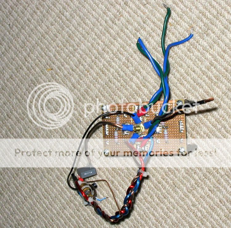
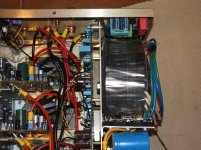
I've added some pictures, the toroid should be obvious, it's got a strip of mu-metal wrapped arround it, the "green" card mounted on the bulkhead oposite the transformer is the x-over card.
I've seen other power-amplifiers out there with some fairly beefy transformers with electronic circuits in very close proximity.
Obviously that can be made to work, otherwise these amplifiers would have been unsellable..
Any comments/ suggestions??
Everything is hooked up and playing, but there is, surprise, some hum.
Now, this is not of the extreme kind that would indicate a bad ground-loop or something, it is a faint but audible buzz that can be heard in the listening position when no music is playing, i.e. too much to be acceptable.
I tried lifting the ground point between input RCA and chassis and connecting ground to the chassis from the reservoir capacitor star-point. This did not make any difference.
I allso tried running a direct ground connection from the starpoint to the x-over card with the card-to-amplifier signal wires shield grounded only in one end. This led to a slight increase in hum-level.
This has led me to conclude, so far, that rather than a grounding problem, I might have an issue with hum being induced directly in to the low-level circuitry.
Perhaps this is inevitable considering the size and placement of the toroid relative to the low-level active -xover card..
In this case, I'm only left with Tony's alternative; move the transformer, unless it is possible to improve shielding somehow??
I've added some pictures, the toroid should be obvious, it's got a strip of mu-metal wrapped arround it, the "green" card mounted on the bulkhead oposite the transformer is the x-over card.
I've seen other power-amplifiers out there with some fairly beefy transformers with electronic circuits in very close proximity.
Obviously that can be made to work, otherwise these amplifiers would have been unsellable..
Any comments/ suggestions??
Attachments
Seeing the layout I'd almost bet that you are getting radiation out of your transfromer direct into the crossover cards. I think you will find that the maximum emi from the transformer is out the top and the bottom, if you had it horizontal (which obviously won't fit in this setup) I suspect your problem would largely disapear.
My playmaster series 200 integrated amp has always had a hum like you describe) the transformer is mounted under the pcb on the right hand side, unsruprisingly the noise on the right channel is worse than that on the left
The only other thing I'd suggest is twisting your Power supply wiring together as tightly as possible. primaries leading to the transformer, secondaries leading to the diode bridge and power to the amps and xover boads all twisted.. for + 0v - twist all three together.
Tony.
Hi Tony,
Again, pardon my lack of continuity following your earlier inputs!
Anyway, Your input is again much appreciated!
Very interresting reply you gave there..
First of all, if a toroid has the greater EMI out from the top and the bottom, the placement of my toroid and x-over card is obviously less than Ideal. Your observation from your amplifier allso seems to substantiate the nature of my problem.
This is good news in the sense that it points to the likely cause of the problem, the bad news is of course that my options for fixing the problems is limited in terms of physical layout.
As I allready described, I have wrapped a strip of high permeability mu-metal arround the circumference of the Toroid, but from your description of the radiated field being more intense from the top and bottom of the transformer, this has pprobably not been a very effective countermeasure.
I have allso covered the bulkhead immideately behind the toroid with the same mu-metal. Wether or not this has improved things, I can not say as I've not tried without. This is something I did sort of anticipating the problems which have now materialized...
Perhaps I can improve matters with more shielding using alternative materials and approaches?
I've seen printed circuit boards covered with a paper/copper-foil laminate on the solder side, obviously for the purpose of shielding..perhaps that could work??
I covered my Torroid with lead sheeting. This reduced the radiated noise quite dramatically, but did not eliminate it. I too could hear it from the listening position but after putting the shield in place I had to get within about 1M to hear the noise.
Your layout looks very tight, so it doesn't look promising to move the crossover board elsewhere Perhaps further to the right so it is more over the PS than the transformer? Ideally on the base of the case but it looks like your amp modules are taking that position.
Rather that moving your toroid out you could consider putting the crossover in a separate metal box (outside of the main amp case) . The power connections are not high current and could still come from the amp case. You will have a bit longer line level connections but I don't think that would matter if your hum problem is gone
Tony.
Your layout looks very tight, so it doesn't look promising to move the crossover board elsewhere
Perhaps further to the right so it is more over the PS than the transformer? Ideally on the base of the case but it looks like your amp modules are taking that position. Rather that moving your toroid out you could consider putting the crossover in a separate metal box (outside of the main amp case) . The power connections are not high current and could still come from the amp case. You will have a bit longer line level connections but I don't think that would matter if your hum problem is gone
Tony.
Tony,
It is perhaps noty too apparent from the immages I attached, but There is no scope for moving the X-over card arround, except for removing it from the chassis entirely as you suggested.. I'd rather avoid this as I'd preferr to have everything in one neat package.. but as a last resort...
So you covered your toroid with lead?? wow.. didn't know those things emitted EMI up in to the x-and gamma-ray spectrum!
No, seriously, I've never heard about lead being used for EMI shielding before.. Did you try other materials as well?
If so, was there a big advantage to using lead?
How did you enclose the Toroid?
Considering you experienced a "dramatic effect", further shielding might yet be an avenue of pursuit, If i can get it down to a level where the hum will only be audible 1m or less from the speaker, that will be fine.
Tony,
Dug arround and found some left-over mu-metal foil I knew I had somewhere.
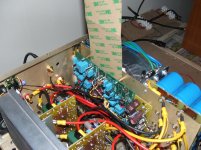
As an experiment, I slid the strip of mu-metall in between the x-over board and the bulkhead behind the transformer. (see pictures)
with my ear to the speaker, I could hear the hum being reduced as the strip hit the bottom of the chassis. Not by a great deal though, but enough to demonstrate that there was an effect.
This further proves your point about this being a radiation issue from the toroid in to the x-over board.
Admittedly, the mu-metal strip didn't cover the entire width of the x-over card, perhaps the effect had been more pronounced if it did.
What I did notice was that when I gradually lifted the strip upp and out again, the hum increased when the strip had been separated from the bottom of the chassis by only a couple of cm, and the hum level seemed to be modulated as the strip was pulled further up, indicating that an EMI field was interacting with/ being distorted by the strip of mu-metal.
This tells me that there is scope for improving matters by placing "stuff" between the transformer and the card in the gap available between the bulkhead and the x-over card. (about 10mm)
But what to use?
Mu-metal is expensive, especially if I need multiple layers to get good effect.
Perhaps just a fat sheet of copper or ordinary mild steel? or some sort of combination?
And Johnferrier; good question..
Dug arround and found some left-over mu-metal foil I knew I had somewhere.
As an experiment, I slid the strip of mu-metall in between the x-over board and the bulkhead behind the transformer. (see pictures)
with my ear to the speaker, I could hear the hum being reduced as the strip hit the bottom of the chassis. Not by a great deal though, but enough to demonstrate that there was an effect.
This further proves your point about this being a radiation issue from the toroid in to the x-over board.
Admittedly, the mu-metal strip didn't cover the entire width of the x-over card, perhaps the effect had been more pronounced if it did.
What I did notice was that when I gradually lifted the strip upp and out again, the hum increased when the strip had been separated from the bottom of the chassis by only a couple of cm, and the hum level seemed to be modulated as the strip was pulled further up, indicating that an EMI field was interacting with/ being distorted by the strip of mu-metal.
This tells me that there is scope for improving matters by placing "stuff" between the transformer and the card in the gap available between the bulkhead and the x-over card. (about 10mm)
But what to use?
Mu-metal is expensive, especially if I need multiple layers to get good effect.
Perhaps just a fat sheet of copper or ordinary mild steel? or some sort of combination?
And Johnferrier; good question..
Attachments
I keep pointing out that iron or low carbon steel is so cheap that its lower effectiveness can be overcome by just using lots
mag fields are redirected/"shorted out" by their preference to travel in the higher permability material
a good approach is to box the supply and the crossover separately with air space/magnetic non-conductor between - the more air space the greater the shielding effectiveness of the layers
"5 sided" open boxes may be needed rather than easier to deal with flat sheets - mag fields really don't like taking sharp turns and can leak around edges, openings - maybe you could get away with simpler "U" shapes
~1 mm soft iron/low carbon steel should be easily bent even at home
Jcx,
Due to my rather compact lay-out, I won't be able to make any box around the x-over card..
Seems my best chance would be to get some mild steel sheet around the transformer..
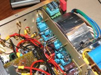
The compartment where the transformer is situated is quite crowded with rectifiers and soft-start circuit wrapped arround on the sides (see pic), so I won't be able to make a full enclosure or even a 5-sided open box..
The best I could hope for, would probably be a "wrap" covering the side facing the bulkhead, the top and pottom and the face where you see the black mounting disc and the bolt.
Even though the "sides" will remain open, this should at least create a magnetic path that the EMI from the transformer could follow?
Would this be effective?
Due to my rather compact lay-out, I won't be able to make any box around the x-over card..
Seems my best chance would be to get some mild steel sheet around the transformer..
The compartment where the transformer is situated is quite crowded with rectifiers and soft-start circuit wrapped arround on the sides (see pic), so I won't be able to make a full enclosure or even a 5-sided open box..
The best I could hope for, would probably be a "wrap" covering the side facing the bulkhead, the top and pottom and the face where you see the black mounting disc and the bolt.
Even though the "sides" will remain open, this should at least create a magnetic path that the EMI from the transformer could follow?
Would this be effective?
Attachments
- Status
- This old topic is closed. If you want to reopen this topic, contact a moderator using the "Report Post" button.
- Home
- Amplifiers
- Power Supplies
- A Grounding challenge , please help..