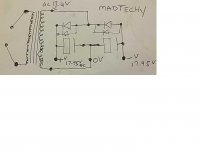
Hi andy it is just a product of my thought . i like to salvage parts from old discarded electronic equipment and this would be a way to use single winding transformers to power dual rail amplifiers. im guessing the current would be shared between the rails so maybe less than half the current per rail.
And DF96 do you think it would have approx double the ripple ????. i will dig out my old scope later and have a look at this circuit when it has a load attached.
Regards Mark
And DF96 do you think it would have approx double the ripple ????. i will dig out my old scope later and have a look at this circuit when it has a load attached.
Regards Mark
Personally I would build a Buck Regulator to generate a -ve supply from the +ve.
If space allowed I would also consider using the LT to drive an SMPS with the required split secondary.
If you only want low current - ie Op-Amp level, then you could employ two resistors in series across the supply and use the junction as 0V but this is only good at low current.
You could also employ two regulators, one on top of the other, the junction forming a psuedo 0V.
Last edited:
Cirrus Logic
This is how Cirrus Logic does it on their evaluation boards.
If its good enough for them I reckon its good enough.
See page 17.
http://www.cirrus.com/en/pubs/rdDatasheet/cs4392eb-1.pdf
This is how Cirrus Logic does it on their evaluation boards.
If its good enough for them I reckon its good enough.
See page 17.
http://www.cirrus.com/en/pubs/rdDatasheet/cs4392eb-1.pdf
This is how Cirrus Logic does it on their evaluation boards.
If its good enough for them I reckon its good enough.
See page 17.
http://www.cirrus.com/en/pubs/rdDatasheet/cs4392eb-1.pdf
That's not a rectifier circuit (those are zeners in the Cirrus Logic circuit).
See page 9.
http://www.cirrus.com/en/pubs/rdDatasheet/cdb4396-1B1.pdf
Crystal supply a single rail wall wart with their evaluation boards and this is how they achieve a split rail supply.
http://www.cirrus.com/en/pubs/rdDatasheet/cdb4396-1B1.pdf
Crystal supply a single rail wall wart with their evaluation boards and this is how they achieve a split rail supply.
Last edited:
The ripple will be roughly twice the amplitude, and exactly half the frequency of a full-wave rectifier. That means that a given RC smoothing arrangement will give output ripple four times larger than a full-wave. You will pick up an extra factor of 2 for each RC stage, simple because of the lower frequency. Solution is to use bigger smoothing caps.
See page 9.
http://www.cirrus.com/en/pubs/rdDatasheet/cdb4396-1B1.pdf
Crystal supply a single rail wall wart with their evaluation boards and this is how they achieve a split rail supply.
Thankyou DF96.
Hi Hotiron that is not the same circuit . That is a zener stabilizer i think.
I dont think there is anything new with the circuit i posted and im sure it has been built many times before and many years ago too. I couldnt find anything much about it on the web and when i seached this forum i still couldnt find it . so i posted it to share with the diy comunity has i have in the past seen posts requiring maybe somthing like this.Maybe the ripple will be a big reason not to use it.
SMPS are not my choice of PSU for an amplifier. My F4 uses CLCLC and massive, correctly specified transformers. Hunting around I managed to get the required 500VA toroidals for £28 each.
I'm always into a bargain though. I was just offerring my thoughts.
The CIRRUS is effectively doing what I suggested, using two regulators. You, however, will be limited by the amount of current you will be able to draw before regulation becomes very poor.
This is a very basic interpretation of how to achieve + and - rails from a single DC supply.
Bear in mind though that 0V is a psuedo 0V. -ve is actually 0V - 0V is actually Vreg1 and +ve is actually Vreg1 + Vreg2.
This is not an issue if the PSU is not referenced to any other supply. If the PSU is FLOATING, ie not referenced to any other power rail, you could equally argue that +ve is 0V and 0V is -Vreg1 and -ve is -Vreg1 - Vreg2.
Do please bear in mind that both regulators are POSITIVE regulators, referenced to (what I marked as -ve).
I'm always into a bargain though. I was just offerring my thoughts.
The CIRRUS is effectively doing what I suggested, using two regulators. You, however, will be limited by the amount of current you will be able to draw before regulation becomes very poor.
An externally hosted image should be here but it was not working when we last tested it.
This is a very basic interpretation of how to achieve + and - rails from a single DC supply.
Bear in mind though that 0V is a psuedo 0V. -ve is actually 0V - 0V is actually Vreg1 and +ve is actually Vreg1 + Vreg2.
This is not an issue if the PSU is not referenced to any other supply. If the PSU is FLOATING, ie not referenced to any other power rail, you could equally argue that +ve is 0V and 0V is -Vreg1 and -ve is -Vreg1 - Vreg2.
Do please bear in mind that both regulators are POSITIVE regulators, referenced to (what I marked as -ve).
Last edited:
That looks good Andy, a power opamp works very well also, TDA2030 or similar.
http://www.diyaudio.com/forums/power-supplies/82681-convert-single-dual-supply-2.html
see post #15
Here are some other methods.
http://www.sonsivri.com/forum/index.php?topic=23870.0
http://www.diyaudio.com/forums/power-supplies/82681-convert-single-dual-supply-2.html
see post #15
Here are some other methods.
http://www.sonsivri.com/forum/index.php?topic=23870.0
Last edited:
Hi madtecchy Yes the top one is zener stabilizer that comes after the rail splitter rectifier the bottom one is what I am looking at, it works very well indeed.
Hot iron please accept my appology.
Yes that is the circuit . And thankyou for sharing that link it is usefull.
Andy nice price on the trafo's. im looking for a nice circuit for two pair genuine toshiba 2sa1302 2sc3281.
Also i agree with using correctly specified transformers for the job.
I find it a good exercise for the failing gray matter to see what can be done from the junk box just because it can . I like electronics and i love music as i guess most members do.
Im running a good ole stereo lm3886 amp at the moment and enjoying it very much. i Have found they can be a fickle little beast with bad layout.
Regards

SMPS are not my choice of PSU for an amplifier. My F4 uses CLCLC and massive, correctly specified transformers.
I have a ton of laptop SMPS power supplies and used two connected in series to get the CT ground for a Zen V5 with +/- 19 volt rails (four laptop supplies total) and its sounds pretty good. Even a friend with "Golden Ears" and very expensive Mark Levinsen equip was impressed...
http://www.diyaudio.com/forums/pass-labs/86012-papa-i-want-have-zen-v5-29.html#post2379427
I will be trying a full blown F5 build with the same concept - no need for huge caps either. Each power supply is good for 120 - 150 watts, so like haveing a 600VA power supply... call me crazy...
Last edited:
I have a ton of laptop SMPS power supplies and used two connected in series to get the CT ground for a Zen V5 with +/- 19 volt rails (four laptop supplies total) and its sounds pretty good. Even a friend with "Golden Ears" and very expensive Mark Levinsen equip was impressed...
http://www.diyaudio.com/forums/pass-labs/86012-papa-i-want-have-zen-v5-29.html#post2379427
I will be trying a full blown F5 build with the same concept - no need for huge caps either. Each power supply is good for 120 - 150 watts, so like haveing a 600VA power supply... call me crazy...
I tried a couple 19 volt lappy psu's in series and ran lm3886 wich normally uses a moderate 200 va Holmgren toroid. With the lappy smps i can only describe what i heard as a dip in frequency response around the mid area. I know the voltage was a little low but my speakers are 91db sensitivity at approx 4 ohm and wasnt trying to push it to hard. Lots more scope to experoment here. a big problem maybe. i left my normal smoothing caps in circuit and the value of these may be affecting the smps.
Last edited:
- Status
- This old topic is closed. If you want to reopen this topic, contact a moderator using the "Report Post" button.
- Home
- Amplifiers
- Power Supplies
- Dual rail from trafo with no CT?????