Yes, there is no point in using a kmultiplier between the shunt and the load.
It would be totally counterproductive..... we made a lot of work lowering the shunt output imp and making it stable with a film cap in the output .... in one of my best builds I even eliminated local decoupling caps in the input amp, getting much faster and detailed sound.... why would we strangle all that using a large cap (k mult) in between ?
It would be totally counterproductive..... we made a lot of work lowering the shunt output imp and making it stable with a film cap in the output .... in one of my best builds I even eliminated local decoupling caps in the input amp, getting much faster and detailed sound.... why would we strangle all that using a large cap (k mult) in between ?
This sounds wonky !.......... .... in one of my best builds I even eliminated local decoupling caps in the input amp,...........
And this confirms the sound is wonky !getting much faster and detailed sound....
Andrew, it could be that removing the local decoupling also removed a resonance, and because of this the circuit works better despite the increased supply inductance. These things are not always straightforward. Of course you could be right. It would take some investigation to see exactly what effect RC's changes had on the rail behavior.
This sounds wonky !And this confirms the sound is wonky !
Hi Andrew....
")
What do you mean by wonky ? Do you mean I am having a pleasurable listening session with un unstable system ?
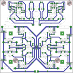
Could someone put eyes on this layout abd see if you spot a problem. I started to solder in the wires from the prereg and the little amount of juice left in the caps exposed what appears to be a short. I cannot find it on the board or the layout, but perhaps I am looking to hard.
Attachments
The output caps do not fill immediately when you apply power. They ramp up too slowly to cause a spark. I don't think the spark in itself would indicate a short.
Maybe something got hidden under the caps when soldering and is causing a short? I had that problem when I got a board wet. The water caused a bridge to form through electrolysis.
Maybe something got hidden under the caps when soldering and is causing a short? I had that problem when I got a board wet. The water caused a bridge to form through electrolysis.
- Home
- Amplifiers
- Power Supplies
- Keantoken's CFP cap multiplier