Do you have examples of such cores?Hi everybody,
I wonder is there anyone designed an E-I ferrite core? I want to ask a question
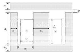
Why is the width of I core is equal to the width of center of E-core? (in many datasheets) wi=wb
An externally hosted image should be here but it was not working when we last tested it.
Thank you so much!
I only find examples having areas identical to the outer legs, or even smaller, as in this case:
http://www.alliancemagnetics.com/pdf/EI_Core_Ferrite.pdf
Hi,
The geometry has to do with minimising waste and the flow of flux around the magnetic circuit.
Start with the magnetic circuit.
Take a flux passing down the left leg (of the E lying on it's back) and an identical flux flowing down the right leg.
These will turn the corner and flow towards the middle. Since the flux in the vertical is identical to the horizontal flow the areas of these legs and the bottom of the E must be the same.
The flux arrives at the middle junction. Here the two flux flow routes sum to double and flow up the middle of the E. Double the flow due to the summ requires double the iron area. That makes the the width of the middle E leg exactly twice the width of the previous legs.
When the flux flow gets to the top, the flux flow splits into two and flows away from the middle leg into the I. Again the width of the I matches the width of the top & bottom E legs.
Now consider cutting these metal pieces.
Join two Es together to make a big figure 8.
The Is are the pieces stamped out to form the winding gap.
The length of the I exactly matches half the Depth of the E gap.
From the 8 you get two Es and two Is. The E&Is add up to exactly 100% of the metal area. If the stamping machine is exactly set up with new cutters then the wastage is zero.
The clever bit is ensuring they get no sharp edge due to shearing the plate. The sharps would cut through the insulation. I don't know how they do that, certainly not by hand.
Hi, Andrew T.
Thanks for your explanation. However, I am little bit confusing. According to you, is that the width of left and right leg also need to equal to width of I-core( this is not true in reality)? If always the width of I-core equals that of center of E-core why some manufacturers make them different( I do not think it is not hard to make them equal)
Thanks!
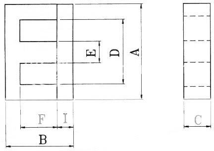
C=I
D=4I
E=2I
F=3I
B=F+2I=5I
A=D+2I=6I
This arrangement gives zero waste and more importantly gives equal flux per unit of width.
If you need more window area, then you cannot have zero waste. But bigger window area can still match all the flux flows per unit of width.
D=4I
E=2I
F=3I
B=F+2I=5I
A=D+2I=6I
This arrangement gives zero waste and more importantly gives equal flux per unit of width.
If you need more window area, then you cannot have zero waste. But bigger window area can still match all the flux flows per unit of width.
Last edited:
Ferrite cores are not stamped. Ferrite cores can be made in lots of funny shapes without scrap.
But still, the middle leg of the E core is typically double the area of the outer legs, the I part and the back of the E to get the same flux density everywhere.
That gives:
E = 2I
B = F + 2I
A = D + 2I
EIR cores are not comparable though, having a round center leg. What about them?
But still, the middle leg of the E core is typically double the area of the outer legs, the I part and the back of the E to get the same flux density everywhere.
That gives:
E = 2I
B = F + 2I
A = D + 2I
EIR cores are not comparable though, having a round center leg. What about them?
- Status
- This old topic is closed. If you want to reopen this topic, contact a moderator using the "Report Post" button.
- Home
- Amplifiers
- Power Supplies
- E-I core