Hello SMPS Community
I am working on a SMPS that I would like to use for some amps I want to build. I have some schematics for a CCM PFC and a DC-DC converter. The design could meet class D and 80+ specs according simulation tests. I do however have some questions. I am well rounded in electronics but I need some design help. Here are my specs so far.
PFC Input Voltage
85V - 265V AC 50/60HZ
PFC Output Voltage
400V DC
Current Unknown
DC-DC Converter Output Voltage
+70V 10A -70V 10A
Total Power ~1400W
I am stuck calculating the PFC Output current going to the DC-DC converter. I am thinking I would need 4A that would be 1600W. But such a design requires HUGE inductors for the input choke. Can anyone help me with the required current output from the PFC to the DC-DC converter. I have been working with poweresim to assist in the design.
Topology
CCM PFC with Half Bridge DC-DC
For 1400W you will probably need a bi-phase CCM PFC. That puts about 700W/phase. Here are the calcs I did for a 500W (1KW bi-phase) using a PQ3535 core.
Anyway.. adapted as needed.
Tony
Impressive.....Is that a program that you have saved or did you manually re-calculate all of that?
Just so everyone has an idea of what I am playing with.
PowerEsim - Free SMPS Switching Power Supply / Transformer Design Software
My project file is attached below. Just open it up with no password.
Take a close look at how rediculous the inductor specs are. 8awg wire????
This type of circuit design is new to me so the learning curve is massive. It will be fun and challenging for me.
LETS MAKE SOME POWER!!!!!
Attachments
Hello SMPS Community
I am working on a SMPS that I would like to use for some amps I want to build. I have some schematics for a CCM PFC and a DC-DC converter. The design could meet class D and 80+ specs according simulation tests. I do however have some questions. I am well rounded in electronics but I need some design help. Here are my specs so far.
PFC Input Voltage
85V - 265V AC 50/60HZ
PFC Output Voltage
400V DC
Current Unknown
DC-DC Converter Output Voltage
+70V 10A -70V 10A
Total Power ~1400W
I am stuck calculating the PFC Output current going to the DC-DC converter. I am thinking I would need 4A that would be 1600W. But such a design requires HUGE inductors for the input choke. Can anyone help me with the required current output from the PFC to the DC-DC converter. I have been working with poweresim to assist in the design.
Topology
CCM PFC with Half Bridge DC-DC
If you need 1600W from your PFC then the Peak Inductor current which will be drawn from mains AC should be calculated at worst case which is:
1600/[85X1.414]=13A approx.
You need an inductor which should be capable of handling 12-15A of current easily.
The total PFC output current will be then 4A at 400V output
This is my standard MathCAD file for CCM operation.
For 85Vac and 400Vout you need about a 70% duty cycle. On top of that you will have a ripple current of somewhere between 25-50% of Idc (I used 40% and in my calcs 1400W). So that will be Idc+Delta I/2 where Delta I is the ripple current.
(1600W/(85*1.414))/0/7)+0.4*(1600W/(85*1.414))/0/7)/2=22.8A peak. This is the amount of peak current you have to use for the flux density calculation of Bmax.
The equations from workhorse are correct for the wire diameter as far as estimating what wire gauge would be appropriate.
After that you have to gap the core if you are using Ferrite.
I split your design up into 2 cores running 180 out of phase. You can use a single core running 1 phase but you will probably need a larger core.
As to the wire thickness, For CCM operation you don't have as much of a problem with the harmonics (now as much need for Litz wire).
One more item... AC Inlets (IEC320) are rated for 15A so be careful how much further you push this. Most Server sypplies are derated for low line operation above 1500W.
Anyway. Good luck.
This is my standard MathCAD file for CCM operation.
For 85Vac and 400Vout you need about a 70% duty cycle. On top of that you will have a ripple current of somewhere between 25-50% of Idc (I used 40% and in my calcs 1400W). So that will be Idc+Delta I/2 where Delta I is the ripple current.
(1600W/(85*1.414))/0/7)+0.4*(1600W/(85*1.414))/0/7)/2=22.8A peak. This is the amount of peak current you have to use for the flux density calculation of Bmax.
The equations from workhorse are correct for the wire diameter as far as estimating what wire gauge would be appropriate.
After that you have to gap the core if you are using Ferrite.
I split your design up into 2 cores running 180 out of phase. You can use a single core running 1 phase but you will probably need a larger core.
As to the wire thickness, For CCM operation you don't have as much of a problem with the harmonics (now as much need for Litz wire).
One more item... AC Inlets (IEC320) are rated for 15A so be careful how much further you push this. Most Server sypplies are derated for low line operation above 1500W.
Anyway. Good luck.
Keep in mind I choose a very wide input voltage range. Typically It will be used in the 108-132Vac range. I choose 85-265 to make it universal for other countries. As far as the current draw....This supply will never be used at the max output I would say at the most it will see a 65% load.
Other Notes:
I find it very hard to locate cores and bobbins for specific sizes. Also if the recomended wire size for example is 8AWG using 4 16AWG in parallel should meet the specs failry close.
Is there any advantage of using a transformer style choke vs a toridal?
" find it very hard to locate cores and bobbins for specific sizes. Also if the recomended wire size for example is 8AWG using 4 16AWG in parallel should meet the specs failry close"
Switching freq. is more important than wire gauge. Don't forget about the skin effect.
I suspect the your PFC switch freq. is arround 100 Khz. So a 16 AWG wire will not be fully utilized. That said you can probably utilitize a thinner gauge wire to hande 1600Watts. Remember your not transmitting current over long distances. the wire used in your inductor will be pretty short, especially if your switching frequency is very high. You dont need much inductance if your switching frequency is high.
I would search for a skin effect calculator on the net the provides wire resistance give wire gauge and freq. Then calc power loss and see how small gauge you can get away with.
One recommendation is to use flat magnetic wire since it has more circular mils and will have a lower AC resistance for the given material used. Another method would to use copper foil instead of wire, but you would need to use a e-core, RM8, or PQ type core since it would be very difficuilt to wind foil on a toroid.
Wire Gauge table with skin effect column:
American Wire Gauge table and AWG Electrical Current Load Limits with skin depth frequencies
Vendor that sells flat magnetic wire (online purchases):
Flat Magnet / Specialty Wire
I suspect that a single wire of 15 AWG flat wire will be sufficient to handle 1600W (but I haven't done the math to back it up).
"Is there any advantage of using a transformer style choke vs a toridal?"
Toroids will have better thermal disappation than other types, but will leak more EMI than other designs.
By the way, Winding a transformer with multiple parallel wires becomes difficult. At most I can do is about 4 parallel wires of 19 AWG at a time without running into problems.
I found a good calculator here....TRANSFORMERS
Next question is: Since this is a common mode input choke do I use 50-60Hz for the freq or the 85KHz. Since it is before the bridge rectifier I would assume it uses the supply line freq.
Next question is: Since this is a common mode input choke do I use 50-60Hz for the freq or the 85KHz. Since it is before the bridge rectifier I would assume it uses the supply line freq.
After doing some searching I have found some online common mode choke calculators. They all seem to lean twards 12AWG wire for ~20A. I have no problem finding the wire....but I am having no luck finding a source for anything to wind it on. Anyone know any sources (prefered in the US) that I can check out for either torids or transformer style chokes?
After doing some searching I have found some online common mode choke calculators. They all seem to lean twards 12AWG wire for ~20A. I have no problem finding the wire....but I am having no luck finding a source for anything to wind it on. Anyone know any sources (prefered in the US) that I can check out for either torids or transformer style chokes?
Why don't you just buy a 20A common mode choke:
Digi-Key - M8916-ND (Manufacturer - 8121-RC)
FYI: looks like the Bourns 20A 1mh Common Mode Choke is using 14 gauge wire.
Coil winding Specialists sells toroid cores you can use if you want to roll your own.
Products : CWS ByteMark, largest supplier of toroids, ferrite cores, iron powder cores, MPP cores and RF cores
I was playing with the design software and higher switching frequency drasticly changed L4.
I was looking at the app notes for the Controller IC there is a sample circuit and schematic. The typical Frequency is 133Khz. So Luca you are correct with not needing to be up in the 200 range. The IC will support running at 250KHz but isnt necessary.
Here is the sample datasheet.
http://www.sacg.com.tw/sacweb/marcom/ad/ad/IFX_PowerSolution/Datasheet/AC-DC/PFC%20IC/AN-EVAL-ICE1PCS01-1.pdf
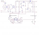
Can someone explain to me why the datasheets only use 1 inductor and the poweresim design software uses 2. I dont understand why the L4 section is present in the schematic that I posted.
I was looking at the app notes for the Controller IC there is a sample circuit and schematic. The typical Frequency is 133Khz. So Luca you are correct with not needing to be up in the 200 range. The IC will support running at 250KHz but isnt necessary.
Here is the sample datasheet.
http://www.sacg.com.tw/sacweb/marcom/ad/ad/IFX_PowerSolution/Datasheet/AC-DC/PFC%20IC/AN-EVAL-ICE1PCS01-1.pdf
Can someone explain to me why the datasheets only use 1 inductor and the poweresim design software uses 2. I dont understand why the L4 section is present in the schematic that I posted.
from the number of turns you make me believe that you gonna use an ungaped core ????? the switching transistor will blow-up instantly, due to the inductor saturation. however, 7 turns on ungaped EE55 cannot give you more than 300-400uH. Al=6-8uH/ts2.L1 - 1.76 mH (EE55 7 turns)
consider using a kool-mu toroid, at least one 0077083A7 for this power level.
- Status
- This old topic is closed. If you want to reopen this topic, contact a moderator using the "Report Post" button.
- Home
- Amplifiers
- Power Supplies
- DIY SMPS - PFC/DC-DC