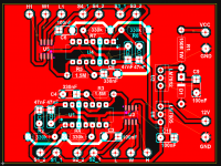
A smidge more progress. Case is ~finished and I gave it a coating of textured paint (in a spray can):
[Wiring to the light bulb limiter and receptacle is done (except an inline fuse that is on order) and the transformer is wired.
How does the bulb limiter work? Is it on a switch so it can be switched in and out? Will it not limit the power going into the transformer?
Do you have a slow start on the toroidal? I had to build one slow start for my 300VA toroidal as it kept blowing the fuse. Plus with the slow start you do not need to route a 240V on/off switch to the front panel.
You have placed the toroidal to the left, is that not going to make the box unbalanced?
The light bulb is wired in series with the upper outlet of the front panel receptacle (I have split the receptacle into 2 circuits). Both bypass the transformer and are wired directly to the IEC socket. The upper outlet is then current limited by the light bulb and can be used to check for faults in a newly constructed power supply and/or the circuit it supplies.
I don't have a soft start on the transformer - it is only 400VA so I didn't think it is warranted. You do bring up a point that I forgot about - there should be a fuse in line with the transformer also. Ah, a bit of rewiring is in order.
We have 120VAC here, not 240. The front panel switch is rated at 6A for 125VAC and is illuminated via a separate 12VDC supply. I'll run that from the 5VDC of the digital pot control board (when THAT is finished).
The transformer makes that side of the case heavier (I still need to build and install the dummy load on that side, which will be fairly hefty as well) but this is a stationary unit and will sit in a cabinet that I will build next:
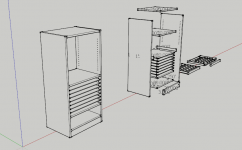
This will house this power supply, my scope and function generator on the top shelves. It will have 8 parts drawers and a larger junk drawer at the bottom, similar to this one:
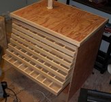
I made that 2 years ago and it is full - I need more space.
I don't have a soft start on the transformer - it is only 400VA so I didn't think it is warranted. You do bring up a point that I forgot about - there should be a fuse in line with the transformer also. Ah, a bit of rewiring is in order.
We have 120VAC here, not 240. The front panel switch is rated at 6A for 125VAC and is illuminated via a separate 12VDC supply. I'll run that from the 5VDC of the digital pot control board (when THAT is finished).
The transformer makes that side of the case heavier (I still need to build and install the dummy load on that side, which will be fairly hefty as well) but this is a stationary unit and will sit in a cabinet that I will build next:

This will house this power supply, my scope and function generator on the top shelves. It will have 8 parts drawers and a larger junk drawer at the bottom, similar to this one:

I made that 2 years ago and it is full - I need more space.
wow I wish you lived nearby so I could contract you to build me one of those parts cabinets, they are truly awesome and i'm rather envious. i'm so sick of rummaging through my ever-increasing parts collection. even despite serious effort and expense for buying many different compartmentalized containers, I still find myself looking for some parts twice. very 
The 400VA toroidal will blow fuse much larger than is necessary without the soft start. Usually these fuses are integrated into the power socket receptacle at the back of the machine, plus a on/off switch (back panel). You need this back-panel on off switch to really switch things off, for example the soft start circuit is always on if you see what I mean (what they call "standby").
The other benefit of the 12V/24v front panel on/off switch is if you spill something at the front and then touch it, or if a wire comes lose around the on/off switch, plus the internal route of high voltage wire from the back to the front dangers. With a 12V on/off switch you simply do not care.
Will you line the individual partitions with aluminium foil to prevent static killing sensitive ICs?
... build me one of those parts cabinets,
Thanks
It isn't really difficult to build, just tedious assembling the drawers. Most of it is just glued together with no mechanical fasteners - some screws through the sides of the cabinet into the fixed shelves.
The biggest challenge (for most) will be cutting the parts accurately. Many parts are exactly the same size, so this helps.
The 400VA toroidal will blow fuse much larger than is necessary without the soft start. Usually these fuses are integrated into the power socket receptacle at the back of the machine, plus a on/off switch (back panel). You need this back-panel on off switch to really switch things off, for example the soft start circuit is always on if you see what I mean (what they call "standby").
The other benefit of the 12V/24v front panel on/off switch is if you spill something at the front and then touch it, or if a wire comes lose around the on/off switch, plus the internal route of high voltage wire from the back to the front dangers. With a 12V on/off switch you simply do not care.
Will you line the individual partitions with aluminium foil to prevent static killing sensitive ICs?
The soft start I would use (if I were to use one) would not require a separate low voltage transformer - it would run from the main transformer. Like this one:
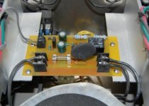
Adding another transformer that is constantly on (or another on/off switch at the back to turn off that transformer) is not my idea of good design. If I were to spill something on the supply, I'd darn well deserve a jolt for being so careless!
I have several values of fuses and I'll use the lowest one possible. In any case, it is there mainly to guard against a transformer fault and in that instance, a larger amperage fuse will open as quickly as a smaller one.
I leave the IC's in their static resistant tube or insert them into that black anti-static foam:
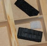
Nice to keep the legs from getting beat up. I've not lost a patient yet!
I have made my Digikey order - as usual, on a Friday. I will have the parts on Monday or Tuesday to finish the supply.
This leaves me with the digital pot circuit board to finish layout on. I have started:
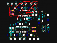
Unfortunately, the X9319 only comes in surface mount. This is my first time doing any type of surface mount board, so a new experience!
There is one thing I need to add to the above layout: a 12V reg for the indicator light in the power switch. It could probably run off the 5VDC, but I like having the 12V reg before the 5V reg, to cut the dissipation down a bit (this is tapping off the 41VDC raw from one of the supplies). Not a big deal to add this in.
I mentioned earlier the ability to link the up/down operation of both pots but I don't think I'll do that. Probably not worth the trouble of adding another front panel switch to facilitate this.
This leaves me with the digital pot circuit board to finish layout on. I have started:

Unfortunately, the X9319 only comes in surface mount. This is my first time doing any type of surface mount board, so a new experience!
There is one thing I need to add to the above layout: a 12V reg for the indicator light in the power switch. It could probably run off the 5VDC, but I like having the 12V reg before the 5V reg, to cut the dissipation down a bit (this is tapping off the 41VDC raw from one of the supplies). Not a big deal to add this in.
I mentioned earlier the ability to link the up/down operation of both pots but I don't think I'll do that. Probably not worth the trouble of adding another front panel switch to facilitate this.
Waiting for parts sux! 
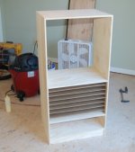
Bored, I started the parts and gear hutch that will house this power supply.
From the front:
And the back:
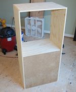
It is 1/2" G1S plywood sides, fixed shelves and top. Joints are glued and air nailed together.
The dividers between the parts drawers are 1/4" hardboard. These support the individual drawers and acts like a lid to keep the parts in their spaces if the unit is moved. I learned this lesson on my bigger unit (shown a few posts ago) when I moved it and had to spend hours sorting.
I'm presently working on the drawers. Many parts and much time waiting for glue to dry.
Bored, I started the parts and gear hutch that will house this power supply.
From the front:

And the back:

It is 1/2" G1S plywood sides, fixed shelves and top. Joints are glued and air nailed together.
The dividers between the parts drawers are 1/4" hardboard. These support the individual drawers and acts like a lid to keep the parts in their spaces if the unit is moved. I learned this lesson on my bigger unit (shown a few posts ago) when I moved it and had to spend hours sorting.
I'm presently working on the drawers. Many parts and much time waiting for glue to dry.
How did you "fix" the hardboard lids/spacers/shelves?
Stopped housing joints?
Is that what we would call dados? No, I used strips of 1/4" hardboard as spacers/supports to separate each lid exactly 1.5". You can see it better here:
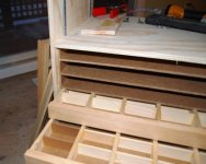
3 drawers are complete and the other 5 are in various stages of completeness. In all, there are 8 drawers, with 36 "cells". Each cell is 3" x 2" x 1.25" deep.
288 cells in this small space will hold a lot of parts and be very convenient to access.
The larger drawer on the bottom (more of a pull out bin) is done. This measures 22" x 16" x 6" deep. This will hold a lot of junk circuit boards and assorted recyclables.
Nice interlude while I wait for parts - building this hutch and assembly of these drawers:
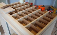
240 (30 per drawer) of those 1/8" hardboard sub-dividers (precision cut) are glued in at 2" spacing.
Handles:
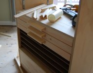
To pull open each drawer. Made from pine, all cuts were made on the tablesaw. Yes, even the cove cut. These pulls are just glued on and that will be plenty strong enough.
I have a bit of an air pressure/vacuum problem with the drawer operation: they fit tightly in the 'slots' and there is not much space for the air that is behind the drawer to go. I'll need to drill some 1" holes in the back at each drawer location to ease this.

240 (30 per drawer) of those 1/8" hardboard sub-dividers (precision cut) are glued in at 2" spacing.
Handles:

To pull open each drawer. Made from pine, all cuts were made on the tablesaw. Yes, even the cove cut. These pulls are just glued on and that will be plenty strong enough.
I have a bit of an air pressure/vacuum problem with the drawer operation: they fit tightly in the 'slots' and there is not much space for the air that is behind the drawer to go. I'll need to drill some 1" holes in the back at each drawer location to ease this.
Parts came 
But a long work day in a distant location has me too tired to do anything.
Drawers for the hutch are fully assembled (finally) and I made 2 adjustable shelves for the 'rack' section.
I noticed one problem with my board layout that is perplexing - the LM317 has the wrong pin out (I normally check, and in this case I thought I did). In spite of this, it still works as it is supposed to. That is odd. I'll correct it, of course, but I'd like to know how this could be.
Ok, I have it sorted out:
View attachment 196431
Quite a bit of monkeying around and I have it where it should be. Current limit goes from a low of 150mA @ 30V to 2.1A at maximum setting - excellent!
At lower voltages, it is possible to set the current limit even lower, to 100mA. I am pleased with this result.
I have made a couple other changes: Added a trimpot in series with the adjust resistor for the LM317. It allows the reference voltage to be set to exactly 15VDC. This will in turn limit the output voltage to exactly 30VDC. I also changed the grounding location for the LM317 to the rectifier side of the sense resistor.
Next is to do a new board layout.
Not an expert on this subject but I have a slightly different approach.
The quality of the output voltage depends on the the quality of the voltage at the base of the output transistors as well as the quality of voltage reference and the general regulator circuitry (LM317 in your case). Of course also the quality of the supply voltage is important, the larger the filter capacitor the better, because the less ripple voltage you have to fight the better it will be.
The LM317 may do an excellent job of eating ripple voltages but prevention is the best cure.
In my circuit the provider of the output current which is subject to huge ripple voltages, is not used to power anything else in the circuit, but instead I derive driver voltages for the reference and for the regulator from another winding which uses its own filter capacitor.
You have almost that in your circuit using a voltage doubler to drive the base of the output transistors (actually I think you only need 3-4 volts more than what is requested at the output, not double...), and that should be pretty much ripple-free as it has its own filter and no serious current demands.
But there are two more improvements, first there is no regulator on that supply. According to my simulation results and some comments on the national docs you can achieve 100db ripple rejection with a FET on top of a zener, and even a zener without a FET would provide much better regulation than raw voltage out of a filter.
Secondly the LM317 is fed from the main supply of the output current and that will see a lot of ripple in its input due to the current drawn (in your case only 2A, in my case 5A). The way to combat this is to increase the filter capacitor, but I would move the LM317 to its own supply and not worry so much about the capacitor. Prevention is the best cure
The quality of the output voltage depends on the the quality of the voltage at the base of the output transistors as well as the quality of voltage reference and the general regulator circuitry (LM317 in your case). Of course also the quality of the supply voltage is important, the larger the filter capacitor the better, because the less ripple voltage you have to fight the better it will be.
Hi akis,
It was not my objective to build a completely ripple free supply. I have no need for such a thing.
In any case, ripple from these supplies is very low, in fact much lower than I initially expected - a bonus!.
My original design had just 4700uF cap filter, to keep copper losses low in the transformers. I bumped that up to 10,000uf only because I happened to have those 2 Cornell Dubilier caps and no other use for them.
The LM317 may do an excellent job of eating ripple voltages but prevention is the best cure.
In my circuit the provider of the output current which is subject to huge ripple voltages, is not used to power anything else in the circuit, but instead I derive driver voltages for the reference and for the regulator from another winding which uses its own filter capacitor.
There are many ways to skin a cat
I try to make things as simple as possible without sacrificing functionality. Figuring out ways to do it efficiently without doubling the parts count is my preferred method.
I considered a separate transformer for the reference voltage in a previous design. I even considered a lead-acid 12V battery (trickle charge when the supply is off). The LM317 wasn't my first choice either - originally I used an opamp with a diode string input reference. Many changes were made before I posted here.
You have almost that in your circuit using a voltage doubler to drive the base of the output transistors (actually I think you only need 3-4 volts more than what is requested at the output, not double...), and that should be pretty much ripple-free as it has its own filter and no serious current demands.
Not only is it nearly ripple free, it is immune to voltage fluctuations in the main supply. Getting 3-4 more volts was not practical or adequate (for the above mentioned immunity). It's easy to throw away if you have more than enough to begin with.
This is your separate supply without the added complication - 2 diodes and one cap.
But there are two more improvements, first there is no regulator on that supply. According to my simulation results and some comments on the national docs you can achieve 100db ripple rejection with a FET on top of a zener, and even a zener without a FET would provide much better regulation than raw voltage out of a filter.
Once again, I wasn't aiming for a totally ripple free supply. Yes, there are ways to improve everything but I know where to draw the line - diminishing returns. I could have (and did try it in simulation) regulated the doubler supply. I could have added a cap multiplier, etc.
Secondly the LM317 is fed from the main supply of the output current and that will see a lot of ripple in its input due to the current drawn (in your case only 2A, in my case 5A). The way to combat this is to increase the filter capacitor, but I would move the LM317 to its own supply and not worry so much about the capacitor. Prevention is the best cure
The LM317 is a very good regulator and has excellent ripple rejection. Add to this the fact that it is just providing a reference voltage (<10VDC) for the LTP and we can put things into perspective. I even went slightly overboard and added a shunt regulator before it.
Prevention IS the best cure...if there is something wrong. That isn't the case here. I expect that this supply, once finished, will meet my needs perfectly.
Thank you for your observations and I wish you luck on your own supply.
The parts and gear hutch is done:
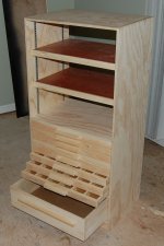
For its size, it is VERY heavy, due to the quantity of 1/4" hardboard used (nearly 2 full 4" x 8" sheets). A low centre of gravity is good in a cabinet that is tall with a small footprint - helps to keep it from tipping as drawers are pulled open.
The two adjustable shelves are pieces of 3/4" maple plywood (formerly cabinet doors - recycle wherever possible) with pine nosing.
I'll move it down to my lab this weekend and start filling it up.
I also want to put some hooks on the side to hang various leads and probes.
I expect this will turn out to be a very useful cabinet indeed.
make two in flat pack form and surface ship them to Scottish Borders. NOW!!!!
- Status
- This old topic is closed. If you want to reopen this topic, contact a moderator using the "Report Post" button.
- Home
- Amplifiers
- Power Supplies
- Lab Power Supply Design / Build
