Have you looked at dissipation requirements when high current is required from one or both supplies at low output voltage?
Hi Andrew,
Not sure how closely you looked over the circuit. Typically, there are no large dissipation issues at low voltage and high current. The supplies are limited to a maximum 2A (via R17 and R20) at any voltage.
A Switching regulator is more likely choice for variable output demands.
I will be getting into switching supplies eventually but I'm not ready yet.
")
So far, all my testing up to this point indicates that this is a pretty good hobby supply. Cheap to build too.
sir MJL21193 im just new to pcb making can i ask what is the software you are using for making the pcb layout...
Hi,
I use Ultiboard. Most all of the footprints shown in the layout were drawn or redrawn by me.
I take it you mean the voltage between the output pin of the LM317 and the negative terminal of the bridge changes. That is inconsequential however as what you need constant really is the voltage between the LM317 output pin and the negative output terminal. You want the current sense resistor R17 to be "outside" the voltage regulating circuit.
It is clear to me now about wat you are saying. I ran the prototype last night both ways and, of course, you are correct...! Again.
My prototype is looking pretty rough. Too many parts swapped out to try various things. I just burned out the LTP when a long resistor lead broke free. I'll need to either clean it up a bit (and replace those T's) or go ahead and make a new board, closer to the final product:

NEW: Changed the ground reference point for the LM317
I have not studied your circuit, if you use a 30+30Vac transformer for <=30Vdc output then the regulating BJTs can see ~45Vdc.Not sure how closely you looked over the circuit. Typically, there are no large dissipation issues at low voltage and high current. The supplies are limited to a maximum 2A
Two channels putting out 2A 5V will need dissipation of ~160W.
That's a loud fan and an efficient heatsink to allow ~80W through each 21193
I have not studied your circuit, if you use a 30+30Vac transformer for <=30Vdc output then the regulating BJTs can see ~45Vdc.
Two channels putting out 2A 5V will need dissipation of ~160W.
That's a loud fan and an efficient heatsink to allow ~80W through each 21193
Ok, when was the last time you were running something that required 2A @ 5VDC? I never have and most likely never will. Designing to reasonable parameters with the end use of the supply in mind saves time and money. If I thought that I would be powering such a load for an extended period, I'd have kept the second pass transistor (mulitap transformers aren't cheap and would add MUCH complexity to the circuit).
Your worst case figuring above is high in any case, as the transformers I'll use are each 26VAC (not a single primary and CT secondary). That would be less than 60W dissipation. I believe a single MJL21194 can handle 60W with a descent heatsink and no fan required.
will they allow 30Vdc and 2A with both current limit circuitry and with regulator?the transformers I'll use are each 26VAC (not a single primary and CT secondary).
will they allow 30Vdc and 2A with both current limit circuitry and with regulator?
It has thus far.
Unloaded AC out is ~28.5V and the transformers are rated at 2.8A with 15% regulation @ full rated load. If limited to 2A, that equates to about 10% regulation at full load, still enough to give me 30VDC @ 2A. Current limiter only starts cutting base drive at Q1 at around 2.1A - this still needs some fine tuning but that is the target.
I'm pretty sure a 26V transformer is a little on the low side for 30V, but if the load is light compared to the current rating of the transformer it should be enough as long as the mains voltage is not low.
I'd use a 30V >=3.6A transformer for a 30V/2A output requirement. Actually, just having a center tap can be useful to reduce power dissipation though so you can use standard transformers with good results for tap-changing circuits.
I used the 36V CT 3.5A transformer from one of those old integrated record player-tape-tuner combos to make a 0-36V, 0-2A bench supply. The winding originally used to power the tape deck and tuner was perfect for powering the "floating" regulator circuit and panel meters with +12V, +5V and -5V referenced to the positive output terminal.
IIRC I made the voltage setting go all the way up to 42V but at full load it will drop out of regulation before reaching that high.
Attachments
I tried simulating a 26V 2.8A 15% regulation transformer connected to a bridge-rectifier feeding a 10mF capacitor and finally a DC load of 2A and I get:
transformer peak current 7.0A
transformer RMS current 3.4A
transformer rectified average current 2.0A (same as output current)
(=> crest factor 2.1 and form factor 1.7)
output peak voltage 31.4V
output valley voltage 30.4V (!)
at nominal line and neglecting transformer leakage inductance. Leakage inductance will reduce output voltage further but also decrease input RMS and peak currents. The transformer may or may not be within its current rating depending on this.
Even though the transformer may be overloaded at 3.4A it will still take a long time for it to overheat with "just" 50% extra loss in the windings. It looks like the maximum continuous output current that won't overheat the transformer is about 1.6A. At that current the voltage might be enough to let you have 30V output but my model isn't really accurate enough to say anything about that. 1A 30V shouldn't be a problem though.
Last edited:
I'm pretty sure a 26V transformer is a little on the low side for 30V
It is.
Some tinkering this evening (after I cleaned up the prototype) and I have nearly 4VDC drop when drawing 2A at 30V.
Waiting in the weeds is a dual secondary Plitron I bought a year and a half ago. It is 30-0, 30-0 rated for 400VA so it has the umph needed to power this supply and I don't have any other plans for it. I connected it and it has no problem delivering 2A at 30VDC through this regulator. Slight drop at the output (~.7V) but I can certainly live with that.
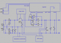
A worthy addition to the supply is a simple shunt regulator before the LM317:

This does a few good things:
- reduce the voltage at the LM to allow it to run cooler.
- reduces ripple at the LM, thereby reducing ripple considerably at the output.
- further isolates the LM from the raw supply, making it more immune to voltage and current fluctuation in the raw supply.
This does a few good things:
- reduce the voltage at the LM to allow it to run cooler.
- reduces ripple at the LM, thereby reducing ripple considerably at the output.
- further isolates the LM from the raw supply, making it more immune to voltage and current fluctuation in the raw supply.
Updated schematic:

Some changes include the new pre-reg shunt. Some resistor values have changed - had an extended tinkering session last night and further refined this.
Nothing written in stone yet, all is subject to change.
New board:

This I will etch and use as my new prototype.
Some changes include the new pre-reg shunt. Some resistor values have changed - had an extended tinkering session last night and further refined this.
Nothing written in stone yet, all is subject to change.
New board:
This I will etch and use as my new prototype.

Success! 2 small things that needed to be changed:
- R9 from 220 to 1K to set the correct reference voltage (ideally ~10V).
- R1 from 10K to 22K, this was getting too hot, dropping a maximum 70V at ~7mA. Even running 2 to 3mA at the base of Q1 is enough for well over 2A at the output.
Everything else was roses, once it was "dialed" in. Constant current (set in this instance at 1.6A) deviation was just 20mA when driving an 8 ohm load from 30V down to 15V. This is actually much better than I expected.
As configured, the maximum current into any load at any voltage is ~2.5A and since the raw supply has more capacity than the earlier version, I will leave that current ceiling as is. I also want to go back and add the second pass transistor back in to spread the current and dissipation over 2 devices instead of one. I have a bunch of MJL21194's anyway, just waiting to be used.
So, back to the layout program to do the final board revision.


I'll try to make this psu on prototype board
It is possible for sure. It doesn't have stability problems so layout isn't critical.
I tried to breadboard it but gave up - too many parts for me. I hate breadboard anyway, I'd much rather spend 30 minutes or so making a board. At least then I can get parts soldered in properly and keep things organized.
Refined the layout a bit more:

And made a pair:

Ready to populate. Boards are 10cm x 12cm.
Last edited:
how do you get the screenprint on to the component side?
I use double sided board (I have a stack of this I got cheap) and etch the silkscreen in:

I mostly only do that on the final revision / finished product. I like having as much information on the SS as possible, to avoid mistakes. Component values, etc.
Some of the features I would like to incorporate into the design:
- Adjustable voltage. As planned, 0 - 30VDC
- Isolated dual supplies, independently adjustable that can be used on their own or put in series to form either a split 30VDC supply or a single 60VDC. When put in parallel, the 2 supplies can give double the current.
- Adjustable current limit for both supplies.
- Built in analogue voltmeter and ammeter on both supplies.
- Built in current limited receptacle. Current limiter in this case is a regular incandescent light bulb in series with the mans. This is for first powering up external power supplies. The bulb will have a bypass switch.
Another feature I want to include in the power supply case is a series of high power dummy loads, for load testing external circuits (amps, etc.). Something like 2, 4, 8, 16 and 32 ohms, each capable of handling at least 100W. I think this is a convenient place to have it, as it won't take up much space and it seems like the most logical place to put it.
This could be banks of cement resistors or another possibility is nichrome wire. I have some from a burned out heatgun that might be enough.
One possibility is a 5 position rotary switch to select the impedance and 2 binding posts to connect to the circuit being tested. Another way is a series of 4 single pole switches, each can put an additional load across the posts (there would already be a 32 ohm load permanently attached to the posts). Button for "16 ohms" would put a 32 ohm load in parallel, "8 ohm" button would put a 16 ohm load, and so on. I like this approach better than the rotary one for a couple of reasons:
1. Better power handling in single pole switch. High current rotary switches are not cheap.
2. As the load goes lower, the power handling goes up, due to the added resistors.
- Status
- This old topic is closed. If you want to reopen this topic, contact a moderator using the "Report Post" button.
- Home
- Amplifiers
- Power Supplies
- Lab Power Supply Design / Build