constant at 100 mA? Current limiting is a dynamic linear process just like voltage regulation. Hysteresis is neither needed nor desired in a current limiter. Oscillations or instability of the control loop are no more (or less) of an issue than in any voltage regulator.
OK this is how it (does not) work in my case:
A sense resistor raises approx 150mV at the desired current limit level.
A current monitor chip (INA170) senses that voltage and produces a ground reference voltage of 1.20V at its output pin.
This voltage is tied to the positive input of an op-amp.
The negative input is attached to a very stable 1.20V.
When the positive input reaches and exceeds 1.20V, which is what happens when we reach and exceed the current limit level, the op-amp swings wildely to positive rail. The op-amp is OPA340 which works off single supply and can swing from ground to rail.
This voltage (supply rail) is then fed to the base of an NPN transistor (the current limit action) which shorts the voltage reference which drives the voltage regulator transistors.
This has the effect of bringing the output voltrage to almost ground, and as the output voltage falls the error condition (cuurent limit breached) is removed!
At that point the op-amp abrupty and suddenly swings to ground making the NPN limit action transistor go open collector, which allows the voltage reference to drive the voltage regulators to full voltage.
The output rises until it breaches the current limit, and the cycle repeats.
Such a design has way too many poles at relatively low frequency to be stable without some kind of compensation. It should be doable though. Could you post your schematic?
Otherwise, a common trick that is often used is to use two opamps, one for current regulation and one for voltage regulation. The outputs of these then go to diodes so that the drive to the pass transistor is determined by the amplifier currently demanding the lowest drive.
To be able to use standard opamps the positive output (if using NPN/NMOS pass transistors) is often made the ground reference of the control circuit which has its own supply of say +-12V. Here is an example from HP/Agilent, also including a 4-level transformer tap changer using thyristors:
http://cp.literature.agilent.com/litweb/pdf/5959-5310.pdf
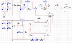
Here is the circuit follwing Andrew's advice to put a constant current source before the voltage regulator.
The voltage reference is derived from a separate supply (not sure if I also need a separate winding), and I divide the 30 Volts into 3 equal ranges so then I can use a rotary switch to select 0-10, 10-20 and 20-30. Via this rotary switch a potentiometer then swipes from 0 to 10 volts, which is added on the base voltage.
This very reliable voltage reference (excluding such exotic considerations as choise of zener and temperature coeffiicient) is then used to drive the base of the voltage regulator transistors (the main transistor needs to be a beefier one to withstand at least 90 Watts, but the simulation software does not have a model for it).
The PNP constant current source limits the current to a predefined level determined by R24, R25 and the two diodes at the base of Q6. This has been put together in a hurry following Andrew's suggestion and I have not yet experimented with the correct way to wire it up.
Outside of your general comments, my question would be what is the correct voltage to drop on R24 ?
Attachments
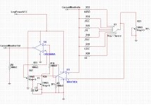
This is the current limiter based on a sense resistor. The output drives an NPN transistor that shorts the voltage reference from the previous diagram (base of Q5, and an addition of a series resistor past the voltage control pot to allows to drop the voltage across) thereby driving the output voltage down.
Attachments
Last edited:
This is the current limiter based on a sense resistor. The output drives an NPN transistgor that shorts the voltage reference from the previous diagram thereby drivign the output voltage down.
Can you put an extra switch bank for the op-amp input? Otherwise the contact resistance is going to dominate on the higher current ranges.
yes, my thought experiment.It's quite obvious that you've never actually designed a current limiter. Your thought experiment above is interesting but impractical.
I have assembled many current limiters but none using a comparator.
Maybe my thoughts are worthless.
Can you put an extra switch bank for the op-amp input? Otherwise the contact resistance is going to dominate on the higher current ranges.
Do not understand that
")
yes, my thought experiment.
I have assembled many current limiters but none using a comparator.
Maybe my thoughts are worthless.
As I see it, the comparator has not got a linear range between "on" and "off", at the point of the theshold it will abruptly go on or off. But to maintain the current at a limit it would need to float gently somewhere in between "on" and "off" depending on the level of the excess current it would be trying to cover for.
What we need is something quite fast, but not as fast as a comparator.
I used the current sense monitor (INA170) with a factor of approximately 10 to 1 at its output (100mV sense in, 1000mV ground referenced voltage out). I fed it to the OPA340 op-amp set a voltage gain between 10 and 22 (currently 22). The output of the op-amp then drives the current limiting transistor and it seems to work well, quite tight around the current limit and no oscillations even when you short the output.
Now it is a matter of tieing it all together and to decide whether the constant current source with its simplicity (1 transistor) is better than the current sense solution which requires 2 chips, 1 transistor and a very accurate voltage reference.
Do not understand that
Only that you have a switch contact in series with a 50mR resistor, and are sensing the voltage across both in series.
A switch contact can easily have 100mR of contact resitance, and be very noisy and erratic in the bargain.
Only that you have a switch contact in series with a 50mR resistor, and are sensing the voltage across both in series.
A switch contact can easily have 100mR of contact resitance, and be very noisy and erratic in the bargain.
Oh yes how true. Hmm I need to think more about this.
Edit: ok so a "standard" 2 x 6 switch will do, as you originally suggested.
Last edited:
Oh yes how true. Hmm I need to think more about this.
Edit: ok so a "standard" 2 x 6 switch will do, as you originally suggested.
Which is why I suggested the extra switch bank, moving the sense point acroos the resistor only. AKA Kelvin or remote sense connection.
I think I have got the sense resistor circuit sorted. Tomorrow I will experiment with Andrew's suggestion of current limiting via a PNP constant current source transistor in between rectifier/filter and voltage regulator transistors. It seems much simpler, requires just one transistor (instead of 2 chips and delicate shunt resistors) and the only sacrifice seems to be a voltage drop of about 1V.

yes, a Vdrop even when the CCS is fully open (passing without current limiting)
The voltage regulator follows this Vdrop and is thus of no consequence to the output.
The mains voltage variation will by far exceed the Vdrop of the CCS when not limiting.
OK I have experimented more and I must say I like the idea because on the face of it there would be no chips involved. But...
As we approach the current limit the CSS starts to conduct less. It is true the voltage regulator that follows will do its best to cope. But this only works when the difference between input-output is great. When I approach the high voltages, eg 30V, then there is only like a couple of volts to play with, and at or right before the current limit level we have already dropped 10 or more volts, so in the end I would have to have a 45 volt supply to be able to get 30 volts at 3 A using this method.
(All the above using huge capacitors so the ripple is really small even at 3A)
Have a look at this:
View attachment 196008
Adjustable voltage, adjustable current limit.
Since you didn't like my breaker idea...
Breaker idea great and I have considered it too, I think I duiscussed it above somewhere. After all what is the point of trying to limit the current , might as well "blow a fuse" and then press a button to reset it.
The new diagram is a bit complicated and did not have enough time to stydy it yet (I have a day job)
if the CCS has moved from Vdrop=100mV to Vdrop=10000mV then it is already current regulating............... When I approach the high voltages, eg 30V, then there is only like a couple of volts to play with, and at or right before the current limit level we have already dropped 10 or more volts,
A bit more gain in the CCS control might make the knee sharper between no current regulation to full current limiting.
The important point is that you (the operator) have chosen a safe maximum limiting current for the circuit being tested.
It also appears from the numbers you are getting that your 30V 3A supply has the wrong transformer fitted to allow for the full range of mains voltages that can be delivered to your home.
Yes it is regulating well before it reaches my chosen 3A, because it is too gradual. I have not got the schematic to show you right now, I have used a second transitor like a Darlington to try and make the base current requirements lower , and derive the base voltage using a Zener 2.4V - the intention was 1V across the emiitter resistor, and 2 x 0.6 across the two transistors, total 2.2V hense the 2.4 V zener.
It seems I need to replace the Zener with some other type of control that will be sharper, similar to what we did with the current sense system.
The chosen transformer is 230v/25V - the supply at my house is well over 240V so I have calculated that I will have approx 33V at the filter output which can give me 30V net.
I could use Shottky diodes as rectifiers may be if I find one that has less voltage drop than the silicon ones ? That might give me an extra volt.
there's part of the problem.The chosen transformer is 230v/25V - the supply at my house is well over 240V so I have calculated that I will have approx 33V at the filter output which can give me 30V net.
It's normal to select a 30Vac transformer to provide a regulated 30Vdc output.
A 25Vac transformer fed with 226Vac ( the old lower limit for a UK supply) will leave no margin for dropout across the regulator when set to 30Vdc output voltage.
A CCS does not gradually become a limiter.
It allows current to pass that is below CCS limit. As the control transistor starts to turn on, the current regulation begins and is complete by the time the control transistor is fully on. That range of current from starting to turn on to fully limiting, can be quite small. Design the CCS to achieve that.
You can use your existing, voltage only supply, to test the CCS across it's output.
The new diagram is a bit complicated and did not have enough time to stydy it yet (I have a day job)
Hi again,
Maybe breakers are too slow.
I'm planning a new lab supply as well - my old supply is also homemade but doesn't have current limit and has only one meter - an ammeter on one leg plus other drawbacks( fixed voltages at 5, 9, 12, 15, 24 and 30V).
I found some nice analogue meters (free, from scrap telephone gear) for a new supply that will be dual 0-30VDC that can be linked as a split supply (+/-)
I've had the circuit for more than a year, playing with it off and on but haven't prototyped it yet.
Look it over, it may have everything you are looking for and it gets over the voltage issue you mentioned above by using a doubler to supply the base voltage for the pass transistor(s).
- Status
- This old topic is closed. If you want to reopen this topic, contact a moderator using the "Report Post" button.
- Home
- Amplifiers
- Power Supplies
- current limiting for power supply