If you want excellent current regulation, then you will probably need a feedback type of regualtor. Using a transistor wired as a constant current source is akin to using a zener voltage follower regulator. It basically works, but the load regulation is poor.Yes it is regulating well before it reaches my chosen 3A, because it is too gradual.
Try something like the following.
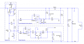
You will need a separate, floating +12V and -12V supply for the opamp circuitry. The common for those is connected to the positive end of the regulator output. You also need precision + and - 5 Volt supplies, probably using two 2 terminal bandgap references (e.g. LM336BZ-5.0). You could use zeners, but the voltage and current settings won't be as accurate or as stable.
You can see the two distinct regulator sections in this schematic. one for voltage, one for current. The output transistor (a power darlingtion, drawn here as a discretes) is constantly driven on by a pull-up resistor, but either regulator can and will "rob" current from its base in order to decrease the output. When the current is lower than the limit, the current regulator opamp tries in vain to increase the output but is blocked by D9. When the current limit is reached (exceeded), it will start to draw current through D9, reducing the output. When that happens, the voltage will decrease so the voltage regulator opamp will rail high to try to increase output but be blocked by D2. The overall regulator always operates in either constant voltage or constant current mode. A simple comparator can be added to the output of one of the opamps to act as an indicator.
With Rsense at 1.78 ohm (and 5 watt) you will be limited to 1.5 A output. You'll need to reduce it to say 0.47 ohm and tweak other values (R16) to set the current limit. Voltage limit can be set by tweaking R3. You can of course use switched resistances in place of either potentiometer. (be aware of what happens during switching... know your break before make or make before break switches).
Attachments
there's part of the problem.
It's normal to select a 30Vac transformer to provide a regulated 30Vdc output.
A 25Vac transformer fed with 226Vac ( the old lower limit for a UK supply) will leave no margin for dropout across the regulator when set to 30Vdc output voltage.
A CCS does not gradually become a limiter.
It allows current to pass that is below CCS limit. As the control transistor starts to turn on, the current regulation begins and is complete by the time the control transistor is fully on. That range of current from starting to turn on to fully limiting, can be quite small. Design the CCS to achieve that.
You can use your existing, voltage only supply, to test the CCS across it's output.
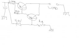
The way I have wired it (see hand drawn stupid diagram)
The CCS transistor is fully on when it is not limiting , otherwise no current would pass.
As the voltage on the emitter resistor increases and as the base voltage is fixed with a zener, that is negative feedback, the base current decreases and the transistor starts to turn off, limiting the flow of current.
This process is gradual well before the "target" current limit.
I am sure the zener is not a clever way and I would need something better there.
Attachments
If you want excellent current regulation, then you will probably need a feedback type of regualtor. Using a transistor wired as a constant current source is akin to using a zener voltage follower regulator. It basically works, but the load regulation is poor.
Try something like the following.
.
Something appears wrong, did you mean to ground the positive rail?
The voltage regulator looks weird... It has no feedback, and its positive input is forever higher than the negative, so the output is always close to +12V, depends how close to the rails the op-amp can go. Say 10V, so the base of the voltage control transistor will be at 10.6V and the emitter at 11.2V, take away 1.2V for the darlington, that'd leave us with 10V at the output with no adjustment or any means of feedback.
So I am confused
")
It looks quite correct to me. Floating power supply is the key. The 12 and 5 volt rails are relative to the positive output terminal. It's the same kind of circuit I mentioned in post 22.
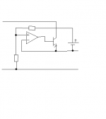
It's pretty easy to make it with just one precision voltage reference though by moving the current adjustment to the noninverting input of the current amplifier. That way you can use a positive reference voltage for both the voltage and current regulators.
Simplified schematic of voltage regulator attached.
Attachments
Last edited:
Ah now I see, what looks like a digital ground is the +out...
I have made the same circuit but simpler on my sim - can all be powered from one power supply and no -Ve required. Please let me know what you think, I have tested it on the sim and it looks great. No current limiting yet, but very good voltage regulation.
I have made the same circuit but simpler on my sim - can all be powered from one power supply and no -Ve required. Please let me know what you think, I have tested it on the sim and it looks great. No current limiting yet, but very good voltage regulation.
Attachments
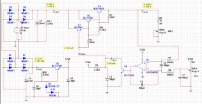
A couple of things:
- The OPA340 isn't going to be happy with 27V supply...
- C1 isn't exactly going to help your transient response either.
- Q4 may be destroyed during downprogramming and/or destroy the pass transistors by reverse breakdown.
- The reference voltage isn't going to be particularly stable.
- The lower legs of both rectifiers are directly in parallel. That's not very good.
A couple of things:
[*]The OPA340 isn't going to be happy with 27V supply...
Indeed, absolute maximum ratings allow for a supply voltage of a mere 5.5 V only!
One of our customers implements an OPA350 in a voltage stablizer fed by the same rail it's going to stabilize using nothing more than a zener and a resistor (and perhaps a C) to bring the opamp supply down to ca. 5 V (from ca. 50 V).
Hi
I will look to improve the circuit and address the points you raised.
1. The OPA340 is seems to be a big mistake on my part. I thought it was a single supply op-amp with Vs 40V and rail-to-rail capability!!!
2. C1 reduced to 1-10uF.
3. Not sure what to do about Q4 or the output transistors.
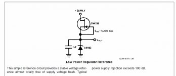
4. The reference voltage on the sim provides a ripple voltage of about +/- 1mV - but I can almost eliminate it with a FET from NS - as shown here
5. The rectifiers - I am trying to have two power sources: one to feed the main power supply output, and the other to provide a stable voltage regardless of the current output of the main supply. I thought in order to do that I need a seperate rectifier and filter completely, but I was trying to save on an extra secondary winding as well. Is there a way to use the saem winding on a transformer to feed more than one rectifiers?
I will look to improve the circuit and address the points you raised.
1. The OPA340 is seems to be a big mistake on my part. I thought it was a single supply op-amp with Vs 40V and rail-to-rail capability!!!
2. C1 reduced to 1-10uF.
3. Not sure what to do about Q4 or the output transistors.
4. The reference voltage on the sim provides a ripple voltage of about +/- 1mV - but I can almost eliminate it with a FET from NS - as shown here
5. The rectifiers - I am trying to have two power sources: one to feed the main power supply output, and the other to provide a stable voltage regardless of the current output of the main supply. I thought in order to do that I need a seperate rectifier and filter completely, but I was trying to save on an extra secondary winding as well. Is there a way to use the saem winding on a transformer to feed more than one rectifiers?
Attachments
Why not use a tried and tested lab power supply circuit?
Reinventing the wheel can be justified if you need special features, but otherwise standard circuit are preferable, as they are plenty of them on the www:
Make Circuits - More Electronics Schematics
0-50V 2A Bench power supply :: circuit diagrams
Bench Power Supply 0-25v @ 0-5amp MicroSyl | MCU Electronics projects
Current Control circuit In The 0-30V Stabilized Variable Power Supply | Power Supply Circuit Diagram
Forum FS Generation
Forum FS Generation
Etc....
- Status
- This old topic is closed. If you want to reopen this topic, contact a moderator using the "Report Post" button.
- Home
- Amplifiers
- Power Supplies
- current limiting for power supply