A variety of larger power amps in pro audio use a big triac for power switching. Then the power switch itself only has to handle the gate. This seriously extends the life of the switch - no arcing and pitting.
I found it works great, but for toroidal transformers the triac (SCRs) switching noise can be significant and make the transformer buzz. However if the transformer has more of an air gap and with higher leakage flux such as an EI core, the switching noise is greatly reduced or non-noticable. Using snubbers will help reduce the noise as well. I found this out, building a slow start circuit for a 120VAC, 1.4KVA toroid. The triac seems quite suitable to switch the toroid onto the line through the current limiting resistor, and then after set time, a relay closes and connects the primary directly to the line. I would bet that switching such a transfo directly onto the line would cause huge surge current vaporizing the switch/relay contacts and/or the mains fuse....actually I know for a fact it will.😱
In my case, the triac is driven by a logic gate and a photo-triac for mains isolation and full wave on. (minus the switching time of course)
In my case, the triac is driven by a logic gate and a photo-triac for mains isolation and full wave on. (minus the switching time of course)
Tks for the info.....
I have used back to back SCRs driving annealing transformers in the past and they work great. Using them for "soft start" makes sense to help with inrush and whatnot. What about using solid state relays on rails? I.E. the type that utilizes 3-32 VDC control inputs. Any thoughts on these being used for protection circuitry? The reason I ask this is that I am sitting a boatload of them from another job and figured I would try them out on the bench supply rails.
I have used back to back SCRs driving annealing transformers in the past and they work great. Using them for "soft start" makes sense to help with inrush and whatnot. What about using solid state relays on rails? I.E. the type that utilizes 3-32 VDC control inputs. Any thoughts on these being used for protection circuitry? The reason I ask this is that I am sitting a boatload of them from another job and figured I would try them out on the bench supply rails.
I have used SSR's to control ovens, just the thing to use with a PID controller and a 2 second cycle.
Just be aware that they are triac based and will introduce some switching noise and they will not tolerate capacitors in the load without some inductance to control dI/dt. They are used in industry frequently for mains loads.
As for protection on the rails they will only switch off at zero current making them slower than a fuse, a mosfet or bipolar device on the DC rails after the filter capacitor would give better protection.
Yep, same here...
Wired some industrial ovens for "burn in" of components using the same methods you describe.
The idea I was thinking of trying utilizes SSRs designed for DC. They are 3-32 VDC controlled with a switching rating of 100VDC @ 10 amps. As mentioned, these things have been laying around here for about 15 years and I was about to toss'em until I thought of this idea. I will try them on the bench supply and see how fast they are using the sillyscope. If they can be used to help in a "current sense" mode circuit it might "tidy" up some of the required component count.
The idea came to me from another job as where we were designing "arc" guards for RF sealing machines utilizing 866A tubes. That circuit was basically a current sense shutoff and was very fast to protect not only the platens but the internal ocsillator components as well. The circuit basically shut down the oscillation by slamming the grid in the main power tube at the same time cancelling whatever "control" level at that time....eh...boring stuff. Anyway, that was the thought anyway, try something similiar using these SSRs on a bench supply to help with R&D of OPSs and whatever else.
Tks a mil for everyones input. If I try this out, "I'll report, you decide", if they blow up.. I'll take carnage pics
Wired some industrial ovens for "burn in" of components using the same methods you describe.
The idea I was thinking of trying utilizes SSRs designed for DC. They are 3-32 VDC controlled with a switching rating of 100VDC @ 10 amps. As mentioned, these things have been laying around here for about 15 years and I was about to toss'em until I thought of this idea. I will try them on the bench supply and see how fast they are using the sillyscope. If they can be used to help in a "current sense" mode circuit it might "tidy" up some of the required component count.
The idea came to me from another job as where we were designing "arc" guards for RF sealing machines utilizing 866A tubes. That circuit was basically a current sense shutoff and was very fast to protect not only the platens but the internal ocsillator components as well. The circuit basically shut down the oscillation by slamming the grid in the main power tube at the same time cancelling whatever "control" level at that time....eh...boring stuff. Anyway, that was the thought anyway, try something similiar using these SSRs on a bench supply to help with R&D of OPSs and whatever else.
Tks a mil for everyones input. If I try this out, "I'll report, you decide", if they blow up..
I'll take carnage picsI've used DC SSRs in several projects.
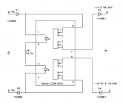
Here is a circuit I've used several times, although the SSRs (6 pin DIP) would run and hide if they saw your power units. 🙂 These are 60 volt low current.
This circuit guarantees that if I'm using two separate DC wall warts for the rails (two DC power plugs on the chasis) that neither rail will come up until *both* wall warts are plugged in. And vise versa both rails die together if either cord is accentally pulled out. Prevents the case of having one rail up and the other down.
D1 and D2 protect against reverse polarity (adaptor with tip negative instead of tip positive). D3 and D4 prevent circuit capacitors from back-feeding the LEDs and keeping the SSR on in the case of either supply being removed.
Attachments
Last edited:
agdr,
Interesting OMRON part. I might try this part and a variation of the circuit in some of the VA stage power in my projects. Tks for the info...
Getting ready to go try the SSR idea in my bench supply as mentioned earlier and see what happens....
Interesting OMRON part. I might try this part and a variation of the circuit in some of the VA stage power in my projects. Tks for the info...
Getting ready to go try the SSR idea in my bench supply as mentioned earlier and see what happens....
Here is a revised diagram with the diode drops added that I forgot to show. 🙂
With the diode drops it would be better to source with 18V if someone was trying to start with 15v, etc. Using schottky diodes would trim some more voltage drop.
Please post your results on your circuit tests! Interesting using them for mains power.
With the diode drops it would be better to source with 18V if someone was trying to start with 15v, etc. Using schottky diodes would trim some more voltage drop.
Please post your results on your circuit tests! Interesting using them for mains power.
Attachments

Last edited:
...also, here is a bunch of helpful SSR application information from Omron on all types - opto/SCR, opto/Triac, opto/transistor, etc. They discuss a power opto/mosfet in this one where a photodiode array triggers the mosfet. They have a nice chart in there of inrush current for various devices (they mention transformers) vs. sizing of the SSR:
http://www.components.omron.com/components/web/PDFLIB.nsf/0/0F7403ADF33E949C85257201007DD5C1/$file/SSR_Tech_Information_0609.pdf
With the G3VM series small-signal opto/mosfets the led triggers the mosfet directly. 1 mS switching time, linear transfer with no distortion, and 2.5kV built in DC transient absorbtion:
http://www.components.omron.com/components/web/PDFLIB.nsf/0/744B2171FDFA7D9F862573D90061B11C/$file/J02C-E-02+G3VM+MOSFET+Relay+brochure+2007.pdf
Solid state relays are good when you switch on and off often. In an amp it's not better than a plain relay.Anyone used solid state relays for mains power?
I am using an SSR to switch mains power for a B22 I just built. The only issue I have is that the SSR buzzes. At first I thought it was the trafos, but when I listen closely, I can definitely tell it is the SSR.
I thought this may be happening due to a DC offset on the 120VAC coming out of the wall. I measured only 17 mV DC though, so I'm not sure if that is enough to cause an issue.
I am using a Crydom D1240 and other than the buzzing, it seems to work perfectly.
Jeff
I thought this may be happening due to a DC offset on the 120VAC coming out of the wall. I measured only 17 mV DC though, so I'm not sure if that is enough to cause an issue.
I am using a Crydom D1240 and other than the buzzing, it seems to work perfectly.
Jeff
Hi,
I have the same problem turning ON the amplifier toroidal transformer at zero crossing to prevent the inrush current. After that it is started buzzing. So what I did to correct the problem was to once it was ON for few seconds, I bypassed it with a relay. No more buzzing. I think the problems it is the voltage dropped across the SSR contact of 6 to 8 volts.
I have the same problem turning ON the amplifier toroidal transformer at zero crossing to prevent the inrush current. After that it is started buzzing. So what I did to correct the problem was to once it was ON for few seconds, I bypassed it with a relay. No more buzzing. I think the problems it is the voltage dropped across the SSR contact of 6 to 8 volts.
Buzzing using SS relays is a real problem with large toroids. I looked at driving the triac with high frequency pulses but nothing was 100% effective.
I went on to develop a working prototype solid state relay that does not exhibit this problem and that uses an opto triac driver (MOC3020 series) driving a power triac that then gets bypassed by a high voltage bi-directional SS relay. The logic drive is simple (one 4011 cmos package) that ensure the triac turns on first and off last.
I went on to develop a working prototype solid state relay that does not exhibit this problem and that uses an opto triac driver (MOC3020 series) driving a power triac that then gets bypassed by a high voltage bi-directional SS relay. The logic drive is simple (one 4011 cmos package) that ensure the triac turns on first and off last.
Attachments
Wouldn't a MOSFET based solid state relay be a good choice here? I would think that as long as one could switch them quickly enough they would work pretty well.
Mike
Mike
Hi,
I am using the OMRON G3NE-220TL-USDC24. NO Zero Crossing Function. I think the buzzing it is coming from the transformer and not from the SSR. It is a low buzzing. You can do a test but you have to be very careful. Add a switch across the output contact. Turn ON the amplifier and then close the switch. See if the buzzing goes away. That is is the way I found how to get rid of the buzzing. Remembered your are working with high voltage. make sure everything it is insulated.
I am using the OMRON G3NE-220TL-USDC24. NO Zero Crossing Function. I think the buzzing it is coming from the transformer and not from the SSR. It is a low buzzing. You can do a test but you have to be very careful. Add a switch across the output contact. Turn ON the amplifier and then close the switch. See if the buzzing goes away. That is is the way I found how to get rid of the buzzing. Remembered your are working with high voltage. make sure everything it is insulated.
Wouldn't a MOSFET based solid state relay be a good choice here? I would think that as long as one could switch them quickly enough they would work pretty well.
Mike
That's in essence what my design is but with the added safety net of the triac to handle the switch on surge. I tested mine on a 650va toroid and it worked faultlessly.
- Status
- Not open for further replies.
- Home
- Amplifiers
- Power Supplies
- Solid State Relays