A question for the solid-state experts:
Background:
My first power amp utilizes a +/-68V supply rail to provide gate-drive headroom for 150W -> 8 ohms. I used cascode stages in a symmetrical VAS, follwed by class-A EF gate drivers to [excellent] Exicon lateral MOSFETs in SF. The sonic results are simply wonderful and it truly paints a 3D picture for each nuance of every song. Only problem was in using such a high supply voltage for my 'household' audio loads. I wanted to keep the PS simple while accounting for the VAS cascode, forward EF bias, and gate drive voltage penalties, probably totaling around 12-15V of lost voltage across the fets at full-swing. Ultimately the thing dissipates too much heat all the time for obvious reasons, despite that I bias it in class-AB (or class-B if you are from the school of Mr. G. Randy Slone).
My next scratch-build concept is to use a +/-55V supply for the FET drains and a small dedicated center-coupled supply (say around +/-70V) for the "smart end" of the amp. I may still build an amp like this for elegance and PSRR; HOWEVER my current project is a retrofit in order to salvage a nice chassis with a good +/-55V power supply (it is a 'blown' SAE amplifier - blown like an abused circuit, not like a dragster intake)...
Enter bootstrapping...Now comes the question:
I want to provide a bootstrap voltage margin to the "smart end" while directly connecting the drains to the +/-55V rails. I am PSRR-paranoid though, so I cooked up this circuit. I have not found any references to lead me on this so naturally I am curious about my prospects. I should actually say that every reference I *have* seen about bootstrapping simply uses a capacitor and a diode or resistor from the incoming supply.
My goal is to "mildly" admit some power to expand the margins, sort of assuming that low/mid-band energy will be available to energize this circuit. Because I prefer elegant biasing techniques for my numerous cascode elements, I don't want to simply use big caps that will force the rails to simply keep their distance from the output via brute force; I want *a little* energy to be rectified and subdued, with a limited voltage value, while not allowing entry of bootstrap diode switching transients. Perhaps this reasoning is questionable; I covet any and all insights.
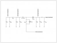
The attached circuit is the present state of my supply design. It is now built, and optimistically I am going to power it up this weekend (obviously at DC it will degenerate to having the bootstrap rails at a diode drop inside the power rails). Can anyone offer pros, cons, expectations, or suspicions about this design? Perhaps someone has some simulation capability and would care to explore it? I am very confident in my PSRR (also using cascodes on diff-amp) but I don't want to be injecting mid-HF junk (without the inductors) if I can compromise and get just a little boost. Basically I'm trying to combine the strengths of something like a flyback converter with low-pass filtering to give some extra emf when needed to avoid drive-clipping (because it is so dissapointing to clip the gate drive when the output devices are right in their wheelhouse).
I understand that this circuit will lag and attenuate compared with a brute-force big-cap bootstrap, but the intention is to be "subtle" and store *some* useful energy during dynamic passages of MUSIC (as compared with the capability to follow LF sine waves on the supply rail), and I am not giving myself any requirement to be able to put the FETs nearly into Vds clip at any time; i.e. I am never going to count on having all 12-15 extra volts available. I would simply like to have 150 nice clean watts into 8 ohms.
Assumptions:
The gates are protected against overvoltage. Output rail to bootstrap connection is at audio-band feedback pickup node (I use multi-band feedback as outlined by W. Marshall Leach). Circuit is entirely polarity-symmetrical but I have shown only the positive side. Amp will be used for "pink" music, not DC or multi-amp bass. Speaker loads will be approximately resistive because I want them that way. EF stage moves about 10mA DC, while the diff-amp, VAS, and biasing nets combine for about another 12mA. The power supply is adequate for the output goals.
Diagram notes:
Original design is degenerate via removal of D1, D2, L1 & C8, with connection between output supply and driver supply. Second approach above would be the same but without this connection and using separate supplies. Jogged line shows wire-to-board from chassis power to amplifier.
Thanks all so much for *any* tips and thoughts!!!
Background:
My first power amp utilizes a +/-68V supply rail to provide gate-drive headroom for 150W -> 8 ohms. I used cascode stages in a symmetrical VAS, follwed by class-A EF gate drivers to [excellent] Exicon lateral MOSFETs in SF. The sonic results are simply wonderful and it truly paints a 3D picture for each nuance of every song. Only problem was in using such a high supply voltage for my 'household' audio loads. I wanted to keep the PS simple while accounting for the VAS cascode, forward EF bias, and gate drive voltage penalties, probably totaling around 12-15V of lost voltage across the fets at full-swing. Ultimately the thing dissipates too much heat all the time for obvious reasons, despite that I bias it in class-AB (or class-B if you are from the school of Mr. G. Randy Slone).
My next scratch-build concept is to use a +/-55V supply for the FET drains and a small dedicated center-coupled supply (say around +/-70V) for the "smart end" of the amp. I may still build an amp like this for elegance and PSRR; HOWEVER my current project is a retrofit in order to salvage a nice chassis with a good +/-55V power supply (it is a 'blown' SAE amplifier - blown like an abused circuit, not like a dragster intake)...
Enter bootstrapping...Now comes the question:
I want to provide a bootstrap voltage margin to the "smart end" while directly connecting the drains to the +/-55V rails. I am PSRR-paranoid though, so I cooked up this circuit. I have not found any references to lead me on this so naturally I am curious about my prospects. I should actually say that every reference I *have* seen about bootstrapping simply uses a capacitor and a diode or resistor from the incoming supply.
My goal is to "mildly" admit some power to expand the margins, sort of assuming that low/mid-band energy will be available to energize this circuit. Because I prefer elegant biasing techniques for my numerous cascode elements, I don't want to simply use big caps that will force the rails to simply keep their distance from the output via brute force; I want *a little* energy to be rectified and subdued, with a limited voltage value, while not allowing entry of bootstrap diode switching transients. Perhaps this reasoning is questionable; I covet any and all insights.
The attached circuit is the present state of my supply design. It is now built, and optimistically I am going to power it up this weekend (obviously at DC it will degenerate to having the bootstrap rails at a diode drop inside the power rails). Can anyone offer pros, cons, expectations, or suspicions about this design? Perhaps someone has some simulation capability and would care to explore it? I am very confident in my PSRR (also using cascodes on diff-amp) but I don't want to be injecting mid-HF junk (without the inductors) if I can compromise and get just a little boost. Basically I'm trying to combine the strengths of something like a flyback converter with low-pass filtering to give some extra emf when needed to avoid drive-clipping (because it is so dissapointing to clip the gate drive when the output devices are right in their wheelhouse).
I understand that this circuit will lag and attenuate compared with a brute-force big-cap bootstrap, but the intention is to be "subtle" and store *some* useful energy during dynamic passages of MUSIC (as compared with the capability to follow LF sine waves on the supply rail), and I am not giving myself any requirement to be able to put the FETs nearly into Vds clip at any time; i.e. I am never going to count on having all 12-15 extra volts available. I would simply like to have 150 nice clean watts into 8 ohms.
Assumptions:
The gates are protected against overvoltage. Output rail to bootstrap connection is at audio-band feedback pickup node (I use multi-band feedback as outlined by W. Marshall Leach). Circuit is entirely polarity-symmetrical but I have shown only the positive side. Amp will be used for "pink" music, not DC or multi-amp bass. Speaker loads will be approximately resistive because I want them that way. EF stage moves about 10mA DC, while the diff-amp, VAS, and biasing nets combine for about another 12mA. The power supply is adequate for the output goals.
Diagram notes:
Original design is degenerate via removal of D1, D2, L1 & C8, with connection between output supply and driver supply. Second approach above would be the same but without this connection and using separate supplies. Jogged line shows wire-to-board from chassis power to amplifier.
Thanks all so much for *any* tips and thoughts!!!
Attachments
- Status
- This old topic is closed. If you want to reopen this topic, contact a moderator using the "Report Post" button.