I have a problem with a very simple PSU circuit, designed to provide +15V and -15V rails via a pair of complementary series regulators. A filter capacitor is connected directly from each pass transistor's base to ground. Any significant value of this capacitance makes the PNP transistor's output unstable. Adding capacitance to the emitter side made the circuit more stable, but not completely. Instability is greatest when the two complementary emitters are connected to each other via a load of the order of 1k. For high (100k) or low (300R) load resistance, stability returns. I've tried several different transistors and capacitors, and the problem is always there.
Other odd behavior. When the circuit oscillates, one of my meters can't give a reading of the DC voltage, or gives a voltage even more negative than the negative supply. The other meter's buzzer circuit mysteriously sounds, for which there is no explanation in the manual (VC9808). During oscillation, meters nearby the circuit measure DC voltage even without leads connected to it, and sometimes even with leads shorted.
I've used emitter followers many times and never had one oscillate. Does anyone have an explanation?
Put up a schematic of what you built. "Simple" doesn't rally describe it.
SOme regulator circuits are not stable without a load. I've certainly serviced enough switchers that needed them.
I have no idea what size this is,so for example, if this is meant to provide about 1 amp, then a 15 ohm resistor will draw that at 15v. Stick a 15-20 ohm resistor across each output. And remember that 1 amp at 15v is 15 watts, so make sure the resistor is up to the task. Or 30 ohms for half an amp. Are they stable loaded like that? Your loading them to each otherr suggest this is needed.
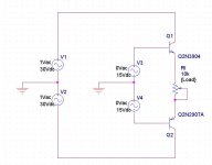
Here it is, but it's so simple that I doubt the schematic will reveal a problem. In the actual circuit there is an RC filtered voltage fed to the bases, but I tried a 9V battery on the PNP base and the problem remains. I've not tried a base stopper yet, but I've never needed one before.
Attachments
This is a well-known feature of emitter followers. If they see a capacitive load they can oscillate. The RF radiation is being picked up on the leads of the nearby meters. You intended to build a PSU but you have actually built a radio transmitter.
Solutions to try: add a resistor in series with the base, right near the base. Or add a resistor in series with the output, so the emitter can't actually see any capacitance directly. In either case use the lowest value which solves the problem for all possible output loads. As a rough guide the base resistor could be a few hundred ohms, the output resistor a few tens of ohms. Alternatively, put a ferrite bead on the base lead.
Solutions to try: add a resistor in series with the base, right near the base. Or add a resistor in series with the output, so the emitter can't actually see any capacitance directly. In either case use the lowest value which solves the problem for all possible output loads. As a rough guide the base resistor could be a few hundred ohms, the output resistor a few tens of ohms. Alternatively, put a ferrite bead on the base lead.
Or even more effective, on the emitter lead.Alternatively, put a ferrite bead on the base lead.
Another possibility, if the application tolerates it, is to solder ceramic capacitors (10 to 100n f.e.) directly between the leads: a trio will absolutely kill any instabilities, but a duo or even a single one might be sufficient: between B and E, f.e.
- Status
- This old topic is closed. If you want to reopen this topic, contact a moderator using the "Report Post" button.
- Home
- Amplifiers
- Power Supplies
- unstable emitter followers and odd behavior