I'm developing a 5.2-amp and need a powerfull smps.
Channels:
5x TDA7293 (50W into 8Ohm)
2x Class D 500W into 4 Ohm
I need +-35V for the TDA7293 and at least +-65V for the class D-amps.
I bought the smps-bible "Switchmode power supply handbook" by Keith Billings, which tells me to use a fullbridge-topology for high power smps.
Now i have a few questions:
Whats the best solution for controlling a smp for an amp? Any IC-recomendations?
Is it a problem for generating 2 different voltages out of one smp?
Most bridge-converters use impulse-transformers instead of fet-drivers and optocouplers - why?
I would use 2 supplys, one for 5 tda's (if 8R load), and one for classD's... both can be half bridge
for controller, if started from 0, use something like mc34025, which is modern smps controller. You could make 2 or even more voltages from one, but I feel its better to have 2, that are deperad for surround and bass. And it's more easy to make 2 that are not that powerfull, also depends a lot on you, have you done anything like this before?
Most that converters? PC's? I have never used transformers, but did fet drivers
Not in such high powerlevels, but i have my book which also includes snubbers and since it's my diploma project, i'm supported by a few professors. One of them is experienced in smps, another one specialises in EMI.And it's more easy to make 2 that are not that powerfull, also depends a lot on you, have you done anything like this before?
I don't remember seeing a schematic with fet-drivers, also the datasheets i've seen before are using transformers.Most that converters? PC's? I have never used transformers, but did fet drivers
But i think fet-drivers works better. Maybe transformers are cheaper and that's why they are used in mass production?
But are integrated controller supporting both transformers and drivers/optocouplers?
If you ask me, they are more bullerproof, high voltage insulation, they can have nice start up done with them... but you do need to calculate them, but after that its just copy and paste all over...I don't remember seeing a schematic with fet-drivers, also the datasheets i've seen before are using transformers.
But i think fet-drivers works better. Maybe transformers are cheaper and that's why they are used in mass production?
But are integrated controller supporting both transformers and drivers/optocouplers?
I don't know, you tell what direction you want to take, I'm sure it can be diffrent for individual
You need to set parameters, under which supply will have to work, input voltage range, output voltage, power, ripple... type of controller(voltage or current), type of feedback
I mean that all easy of will be fun to debug and make it works great
Yes, most have ~1A output, that can drive fets or drivers or even gate trafosBut are integrated controller supporting both transformers and drivers/optocouplers?
I've found here a class D-ic, also including the bridge and feedback:TI tas5630.
In the datasheet, a supply reference design is mentioned, designed for the ic: http://focus.ti.com/lit/ug/slou293/slou293.pdf
It doesn't make sense to design a SMPS when TI delivers a proven one.
Now, a SMPS for my 5xTDA7293 remains and a SMPS for 500W is simpler to design than one for 1,6KW.
Has somebody built Ti's reference smps?
What's the advantage of a halfbridge-smps?I would use 2 supplys, one for 5 tda's (if 8R load), and one for classD's... both can be half bridge
I know many advantages of fullbridge-smps and the only disadvantage is the need of a high-side fet-driver which costs <1€...
Does anybody know a good full bridge-controller?
BTW: Why are some people here preferring impulse-transmitters to fet-drivers?
I like this page for info...
SMPS Switching Power Supply Topologies: Comparison and Selection
and
http://www.onsemi.com/pub_link/Collateral/SMPSRM-D.PDF
SMPS Switching Power Supply Topologies: Comparison and Selection
and
http://www.onsemi.com/pub_link/Collateral/SMPSRM-D.PDF
Last edited:
Half bridge all the way. I've got 10kW pumping through a half bridge in my induction heater.
For power supply applications, where the output is constant voltage, bipolar, square wave, AC only, there is no advantage. There are two strong disadvantages: doubled switching AND conduction losses.
For some power supply applications, a full bridge has some advantage. For instance, a constant-current type bridge is easier to build in PP or full bridge, because a two-winding supply inductor is required for half bridge. If the supply voltage changes quickly, a lot of current will be spent slewing the filter capacitors (which includes the coupling capacitor, when caps to +V and -V are used in the half bridge, as I traditionally do).
There is only one strong advantage I see for full bridge, which is useful where a DC component is required, or where the output must be connected open circuit sometimes. Examples include DC welders, class D amplifiers, motors, electric vehicle drives, etc. In these cases, PWM can be fed to just one side of the 'H', while the other remains locked (in the low state, let's say). This costs double conduction losses, but saves switching on one side. Meanwhile, the output can be switched over a continuous range from +V to -V, without requiring a tiresome bipolar power supply. (A half bridge, in principle, needs a bipolar supply, but this can be provided for AC loads simply with a coupling capacitor.) If a "coasting" feature is required (this would be handy for electric vehicles, when regenerative breaking is not immediately necessary), both sides of the bridge can be turned off completely, leaving the load open circuit. (It will still drive power into the supply if the load voltage pushes above +V, because of the protection diodes; this could only possibly occur in an accelerating downhill case, which is unusual.) Likewise, a "braking" feature is available, by turning on both sides in the "low" state (effectively shorting out the load).
For AC type inverters, such as forward converters, resonant and etc., I don't see any advantage to H bridge. The filter caps aren't any different, you need the same total amount in either case. If you absolutely must use extra transistors, you can hook them in parallel, and get half, instead of double, the power loss!
Tim
Last edited:
when you will meet HV problems around mosfets, and mainly, insulation problems, start to try this:
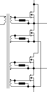
the winding are only 10 turns, all the windings can be made around a single core. the core should be a ferrite core, the form doesn't matter a lot.
toroids or pots act the same.
the command is simple, use a buffer to drive inputs (A & B), the signals from sg3525 are enough, but better with a buffer like UCC27324.
the resistors are 10k 1/4W
the mosfets are N.
it works in a very large range.
Attachments
Nice to read so many experienced people on this complex topic ")
Does anyone know a good information source for building the first smps?
For example, what's an "easy" controller to start with?
What topology i should use?
Is there a well documentated project anywhere to use as example?
Is +/-40V, 5A (per output) a possible target for the first try? (would fit for my 5xTDA7293-Amp)
To Sch3mat1c,
what controls the output of HB, particularily when both switches are off? Parasitics...
Really poor regulation at light loads
HB output voltage is half of that of FB.
what is the benefit of double current flowing through the half resistance vs the current flowing through the double resistance?
DC bus capacitor ripples are unequal too...
1. In the off state, the transformer voltage is determined by the output transformer and choke (assuming forward converter topology, continuous current). When off, the transformer is clamped to ~0V, at the secondary side, by the choke current. This causes ringing current at the secondary, and ringing voltage at the primary, due to leakage inductance and parasitic capacitance; this is easily damped with an R+C across the primary. Voltage returns asymptotically to zero.
When current is discontinuous (due to compact design, or at light load), the voltage is defined only by the OPT impedance. This is a finite impedance, so the voltage is well defined.
If, instead, one were to drive the transformer with a constant voltage at all times (like a phase shift H bridge), one would get ringing current at the primary and ringing voltage at the secondary. This is commonly seen in the rising edge of a half-bridge forward converter. I suppose this might be disadvantageous because the ringing causes the recitifer diodes to switch rapidly (at the resonant frequency, ~MHz?), which will cause excessive heating and RFI. Obviously, this is more of a problem for silicon junction diodes than it is for schottky.
2. I get excellent regulation at light loads. I don't know what problems you have had.
3. Output voltage is half, so you simply need half the primary turns. Obivously, you wind the transformer for the circuit.
4. For the same number of transistors, double current through halved resistance is equal to single current through double resistance. Something about "no free lunches".
5. Why would they be unequal?
Tim
- Status
- This old topic is closed. If you want to reopen this topic, contact a moderator using the "Report Post" button.
- Home
- Amplifiers
- Power Supplies
- Offline full-bridge SMPS