Evening all!
My MOSFET amp (when built) needs 45-55 volt supply. I have a 40V x 500VA transformer (recommended by the amp designer) which in theory will provide 40*1.41=56.4v at the rails.
However I failed to check my home's mains supply which is actually 240V. The trafo is rated at 230V and is giving 46 volts at the secondaries so I'm expecting around 64v at the rails which is almost 10v over the recommended supply.
So my questions are:
1) Is 10 extra volts going to be an issue?
and if it is...
2) what is the simplest and most cost effective way to reduce the voltage to the required level, apart from replacing the trafo with a lower rated model?
Many thanks in advance for any assistance..!
John.
It's not necessarily a problem. If the caps are rated suitably, and also the active devices then the amp should be fine. That 46 volts will drop slightly as the tranny is loaded by a couple of hundred milliamps that the amps probably draw. I assume the amp is a fully worked design with good bias stability etc.
The biggest problem is that the extra voltage causes increases in heat for a given power output.
What's the amp ?
The biggest problem is that the extra voltage causes increases in heat for a given power output.
What's the amp ?
Hey Mooly!
Thanks for your reply. The amp is a 100/160W MOSFET designed by Edwin Paig - here's the link ampli mosfet simple
The caps are rated at 63V and are already purchased! If I could just bring it down to around 60v then it may be OK?
John
Thanks for your reply. The amp is a 100/160W MOSFET designed by Edwin Paig - here's the link ampli mosfet simple
The caps are rated at 63V and are already purchased! If I could just bring it down to around 60v then it may be OK?
John
Hi johnalexwarren,
if your trafo is toroidal type, i suppose it is, then is very easy to unwind couple of turn from secondary side to knok couple volts down.")
You can even calculate turn ratio so you will exactly know how many turn to unwind.
EDIT:
about those caps; i would leave at least 10 V reserve, you dont wont to be top-out with them, thew will "live" longer on smaller voltages
if your trafo is toroidal type, i suppose it is, then is very easy to unwind couple of turn from secondary side to knok couple volts down.
You can even calculate turn ratio so you will exactly know how many turn to unwind.
EDIT:
about those caps; i would leave at least 10 V reserve, you dont wont to be top-out with them, thew will "live" longer on smaller voltages
Last edited:
Another option is to use a Buck step down regulator if you can input DC voltage to your amp.
Check out:
LTC3810 - 100V Current Mode Synchronous Switching Regulator Controller
http://cds.linear.com/docs/Datasheet/3810fb.pdf
Just be sure to add an CLC filter to the output to kill the switching noise. Although the switching frequency is well outside of the audio range (~250 Khz).
Check out:
LTC3810 - 100V Current Mode Synchronous Switching Regulator Controller
http://cds.linear.com/docs/Datasheet/3810fb.pdf
Just be sure to add an CLC filter to the output to kill the switching noise. Although the switching frequency is well outside of the audio range (~250 Khz).
You can use a capacitance multiplier. A capacitance multiplier will significantly reduce ripple in your power rails, and as a side effect it drops the rail voltage by a few volts. It is similar to a regulator, except that it reduces the voltage by a (fairly) constant voltage, rather than producing a constant voltage. This is nice since as the rail voltage sags under load, you will not go under the dropout voltage as might happen with a regulator, and the power dissipation in the series pass transistor of a capacitance multiplier is fairly constant. Refer to Capacitance Multiplier Power Supply Filter
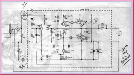
Thanks for the link John... it's quite a classic design that can be traced back to the original Hitachi Lateral Fet application notes. Capable of excellent quality too.
Out of interest are you using HEXFETS or Laterals ?
My thoughts on this are that for normal domestic use a lower supply voltage is more suitable, no higher really than -/+ 45 to 50. I say that because of the problems of heat dissipation in the outputs, that extra voltage makes a big difference. In terms of subjective power output... you wouldn't notice the difference.
That said the higher rail is workable... as long as the PSU caps are rated for it.
Macboys suggestion of a capacitance multiplier is interesting, and while achieving the reduction in voltage as far as the amp goes, it still needs the main reservoir caps to withstand the full output from the tranny. The heat "saved" from the outputs by the lower rail is still produced by the pass transistors in the multiplier.
The heat produced by the amp under domestic conditions isn't such an issue... testing under full output for any length of time is a different matter.
Here's the old Maplin/Hitachi amp,
Attachments
Hello, I think I will build this amp too, my first MosFet amp (probably), so I wanted to know if I can use IRFI9634 and IRFP264 instead of IRFP9240 and IRFP240?
To topic author: You can use LM317HV or LM338 regulators, but I dunno if they can provide enough current. Better take off some windings from trafo, thats the way how I do it.
To topic author: You can use LM317HV or LM338 regulators, but I dunno if they can provide enough current. Better take off some windings from trafo, thats the way how I do it.
Hello, I think I will build this amp too, my first MosFet amp (probably), so I wanted to know if I can use IRFI9634 and IRFP264 instead of IRFP9240 and IRFP240?
Should be OK.
All these amps have no thermal compensation... the circuit was originally designed for laterals and their negative tempco. The HEXFET's will work, but be very careful adjusting bias and make sure no runaway occurs.
Macboys suggestion of a capacitance multiplier is interesting, and while achieving the reduction in voltage as far as the amp goes, it still needs the main reservoir caps to withstand the full output from the tranny. The heat "saved" from the outputs by the lower rail is still produced by the pass transistors in the multiplier.
Yes, a capacitor multiplier doesn't eliminate the need for sufficient reservoir caps. It does however reduce ripple by a significant factor. That is where the name comes from; the ripple voltage on the output is equivalent to using much large reservoir capacitors.
Good point about the heat too. You don't reduce heat overall, but you distribute the heat between the cap.mult. transistors and the amp output transistors. And you put the amp's output transistors into a safer operating point (VCE * IC), so that in theory you can pull more current through them without damage.
- Status
- This old topic is closed. If you want to reopen this topic, contact a moderator using the "Report Post" button.
- Home
- Amplifiers
- Power Supplies
- Need to knock a few volts off..!