Hello everybody on diyAudio,
I've got a challenge for the electrical engineers on the forum.
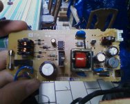
I've pulled a switch mode power supply from an old lexmark printer (got it a few years ago) and I'm trying to incorporate it into a small amp-on-a-chip project. I'm set on this ps because it outputs both 24v and 3.3v, perfect for driving the amp and some decorating LEDs.
Here's the problem: this amp supposedly runs best at 24v, but can operate between 8v-28v. I already know that if I lower the input voltage (say, to 12v) it'll give less gain, which I need for this particular application. This will also allow me to run the case cooling fan (an old CPU cooler) without risking burning it out.
Is there a way (and if so, how?) to lower the 24v output section of this supply, and maintain the 3.3v rail intact? I've been following the traces on the board, and I'm taking a rough guess that if I would be able to modify the driver circuit for the driver ICs, the output could be adjusted.
Also, should I be shielding the enclosure to prevent EMI?
As for filtering, I've noticed one particular fluorescent fixture in my house (on the same breaker as my workbench) generates a lot of buzzing in the speakers when switched on. Is there anything I could/should do about this? The PS has pretty good filtering as it is, I think.
I'd love any help I could get. I need to finish this one quick!
You can't adjust the outputs of the power supply separately. They are in a fixed ratio, determined by the turns ratio of the power transformer. Having said that, however, there are some supplies that have separate feedback paths and if you are lucky, you have one of those. Rare, though.
Shielding is a good idea; those units are practically radio transmitters.
The fluorescent lamp can be a problem; I doubt there is much you can do with it. If the EMI is line propagated you can try ferrites on the power leads. But if it's radiated from the lamp itself you are out of luck, short of screening it with some mesh.
You can't adjust the outputs of the power supply separately.
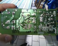
Remember Bob, this is a switching power supply, not a linear one. I should upload pictures of it, but it's controlled by two small 8-pin ICs. One that (I assume) controls the main power MOSFET (i.e. the PWM cycle) for the 24v system and the other (that I assume) controls a secondary MOSFET [positioned after the first] for the 3.3v output.
I would imagine the main FET controls all the output. Each output has its own winding on the transformer and the ratio between the outputs is fixed. The secondary FET might be for the standby supply, which these beasts all have, so it can know when to switch on. The green wire needs to be grounded to make the supply start up.
SMPS providing multiple output voltages, for some the rails are group regulated, for others individually regulated. Or the power source for the lower voltage rail may be taken from the higher voltage rail.
If you can manage to google the function of the chips that should answer the questions.
If you can manage to google the function of the chips that should answer the questions.
If the 3.3 is separately regulated then you can adjust the voltages independently. Changing the higher voltage shouldn't have any effect on the 3.3 in that case. Try it!
It's not the most efficient design, as the losses in the 3.3 regulator have those in the higher voltage section added to them.
It's not the most efficient design, as the losses in the 3.3 regulator have those in the higher voltage section added to them.
Actually, the rectification losses are much less at higher voltages, often enough to offset regulator losses. And it might be the only way to go if you need several tightly regulated voltages.It's not the most efficient design, as the losses in the 3.3 regulator have those in the higher voltage section added to them.
The main problem here is that I don't know how to adjust the output voltage.
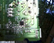
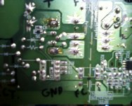
The circuit utilizes this IC (NCP1200A) just after the bridge rectifier, apparently feeding this MOSFET (2SK2793). After the transformer, eventually the power reaches this IC (H34063AP), presumably regulating the 3.3v output through an IC whose datasheet I can't find, but looks like KB1151Y434, or something like that. Oh, and there's an optocoupler (NEC 2501A) connected between the 1200A and the 24v side.


The circuit utilizes this IC (NCP1200A) just after the bridge rectifier, apparently feeding this MOSFET (2SK2793). After the transformer, eventually the power reaches this IC (H34063AP), presumably regulating the 3.3v output through an IC whose datasheet I can't find, but looks like KB1151Y434, or something like that. Oh, and there's an optocoupler (NEC 2501A) connected between the 1200A and the 24v side.


I already know that if I lower the input voltage (say, to 12v) it'll give less gain, which I need for this particular application.
This sounds jolly interesting - a chip amp which senses the power rails and adjusts its gain accordingly. Never come across one that does that - what's the part number?
This sounds jolly interesting - a chip amp which senses the power rails and adjusts its gain accordingly. Never come across one that does that - what's the part number?
Here's the kit. At the 24v it recommends for full power, I think I'm getting more than 10w. Thus, I need to lower the supply somehow.
Still at my workbench, scratching my head as I type this. Any tips would be greatly appreciated. :S
I see - it doesn't adjust the gain, that's fixed at 36dB whatever PSU you use. Your output power will depend on the speakers - the 1% distortion figure into 8R is about 7W, 12W into 4R. Myself I'd not bother trying to adjust the SMPSU (it may well not be possible), just live with the 24V and put a resistor in series with the 12V fan.
Oh, so what you're saying is that by lowering the voltage the THD will just go up? The only thing is that, when connected to this 24v supply the heat sink gets quite hot, hotter than I would have expected it to. Plus, I'm really not looking for a lot of power.
So, to recap what you've said, if I've understood correctly; voltage input will NOT affect volume (output), but only distortion levels? It's better to simply place a resistor or regulator in line with the fan?
I'm still having a hard time understanding that voltage input won't affect output. Ah well, shows how much I know
Keeping the input signal constant, the THD will remain largely constant as the PSU voltage is reduced, until you hit clipping. Those graphs of power vs voltage show where clipping starts to occur.
Quiescent dissipation at 24V I agree is an issue - the datasheet says the chip will typically draw 60mA when sitting idle, that's 1.4W - not going to tax most heatsinks. So long as you can live with this additional 700mW idle power (compared to 12V), there are no disadvantages I can see for running at 24V. As you don't need a lot of power, keep the volume control down low. But its always nice to have power in reserve - at 12V supply you're limited to about 1.5W into 8R.
So from your recap, yes the PSU voltage won't affect the the volume until you run into clipping (which is gross distortion).
For an amplifier, the output voltage will always be the signal input voltage multiplied by the gain, assuming there's no clipping. The PSU voltage only affects where clipping occurs.
Try a series resistor for dropping the voltage to your fan. If it doesn't start up, a paralleled cap with the resistor might help.
Quiescent dissipation at 24V I agree is an issue - the datasheet says the chip will typically draw 60mA when sitting idle, that's 1.4W - not going to tax most heatsinks. So long as you can live with this additional 700mW idle power (compared to 12V), there are no disadvantages I can see for running at 24V. As you don't need a lot of power, keep the volume control down low.
So from your recap, yes the PSU voltage won't affect the the volume until you run into clipping (which is gross distortion).
For an amplifier, the output voltage will always be the signal input voltage multiplied by the gain, assuming there's no clipping. The PSU voltage only affects where clipping occurs.
Try a series resistor for dropping the voltage to your fan. If it doesn't start up, a paralleled cap with the resistor might help.
- Status
- This old topic is closed. If you want to reopen this topic, contact a moderator using the "Report Post" button.
- Home
- Amplifiers
- Power Supplies
- Adjusting a SMPS output