Hi, I thinking to build a discrete regulator for VAS and input stage.
The amplifier not use negative feedback, so I need a very low noise PSU.
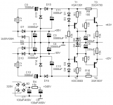
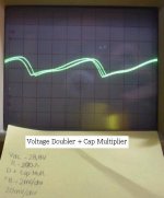
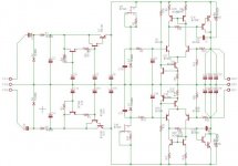
I use a doubler voltage + capacitance multiplier + discrete regulator (I don´t want use another transformer), so with Vac=20Vpp, Vout=27.9V(zener).
Rippley = 5.72uV with Rload = 220ohms (this is 126.81mA)
The components are standard, BC547, BD139(MJE340), BC337, BF245.
A appreciate any feedback about this circuit.
The amplifier not use negative feedback, so I need a very low noise PSU.
I use a doubler voltage + capacitance multiplier + discrete regulator (I don´t want use another transformer), so with Vac=20Vpp, Vout=27.9V(zener).
Rippley = 5.72uV with Rload = 220ohms (this is 126.81mA)
The components are standard, BC547, BD139(MJE340), BC337, BF245.
A appreciate any feedback about this circuit.
Attachments
I don't follow the voltages.
The transformer is 20Vpp but after the first regulator/multiplier you have over 32Vdc.
Is the transformer 6Vac or 12Vac? or something else?
R13 is passing ~2.7mA. R11 is passing ~0.26mA.
Is the rest of the current, ~2.4mA, passing R18?
For a balanced LTP you need Q4 & Q5 to pass the same Id +-1%
Does C7 attenuate the ripple reaching the LTP and thus prevent the LTP passing a ripple correction signal to the Vreg transistors
Last edited:
Hi Andrew.
After the voltage doubler, I don´t have 40V or a near value , I don´t know why. The voltages are in the first picture.
For balanced Iq maybe I can use current mirror with the LPT, as show in the next picture. R11 = R18 = 1k, is too high?
In the new schematic, Vout=27.794V and Vrippley=378uV (after 0.6sec).
BUT Ic´s are differents:
Ic(Q4) = 527uA and Ic(Q5) = 2.607mA ...
Maybe change Q17 for darlington transistor, like BC337+BD139.
I use C7 to reduce the ripple present in the base of Q5. I will try without this capacitor.
Cheers
Edit1
With R11=R18=100 and Darlington output transistor, Ic(Q4) = 1.5785mA and Ic(Q5) = 1.5638mA, this is Iunbalance = 14.667uA.
After the voltage doubler, I don´t have 40V or a near value
, I don´t know why. The voltages are in the first picture.For balanced Iq maybe I can use current mirror with the LPT, as show in the next picture. R11 = R18 = 1k, is too high?
In the new schematic, Vout=27.794V and Vrippley=378uV (after 0.6sec).
BUT Ic´s are differents:
Ic(Q4) = 527uA and Ic(Q5) = 2.607mA ...
Maybe change Q17 for darlington transistor, like BC337+BD139.
I use C7 to reduce the ripple present in the base of Q5. I will try without this capacitor.
Cheers
Edit1
With R11=R18=100 and Darlington output transistor, Ic(Q4) = 1.5785mA and Ic(Q5) = 1.5638mA, this is Iunbalance = 14.667uA.
Attachments
Last edited:
Hi Kevin. Q1-Q3 they aren´t to regulate. This transistors and C3-C4 are the capacitance multiplier.
Capacitance Multiplier Power Supply Filter
The discrete regulator consist in voltage doubler + cap multiplier + regulator.
The regulator is the LPT and Q25/Q17.
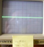
Here, is the version 2 of the regulator, ando some pictures under differents loads. In the next day I hope build the regulator on protoboard and take some photos.
Capacitance Multiplier Power Supply Filter
The discrete regulator consist in voltage doubler + cap multiplier + regulator.
The regulator is the LPT and Q25/Q17.
Here, is the version 2 of the regulator, ando some pictures under differents loads. In the next day I hope build the regulator on protoboard and take some photos.
Attachments
No, I forget write that.1n4148's ???????????
Pspice don´t have 1N400X series.
Diodes aren´t 1N4148 and Q17 is a BD140.
I think, that Your solution is overcomplicated. I want to use something similar. Attached the schematic.
The regulated +/-42V feeding the Vbe multiplier, the first EF stage in my hybrid amplifier, the +/-35V used by the output stage, and the +240V is for the tube VAS.
Sajti
The regulated +/-42V feeding the Vbe multiplier, the first EF stage in my hybrid amplifier, the +/-35V used by the output stage, and the +240V is for the tube VAS.
Sajti
Attachments
Sajti
I am curious about the role of T1 and T2. They create a current source that will stabalize the zener voltage with respect to input voltage changes?
Also, I know that the use of feedback in the audio path is frowned on by many, but need this also apply to power supplies? One more transistor and the circuit could supply a stable voltage with respect to output loading as well as input line changes.
Why not use a TL431 and have a band gap referenced voltage that would be stable with respect to changes in line, load and thermal conditions?
Cheers,
Kevin
Sajti
I am curious about the role of T1 and T2. They create a current source that will stabalize the zener voltage with respect to input voltage changes?Kevin
Yes. This gives much better performance for this simple regulator.
Also, I know that the use of feedback in the audio path is frowned on by many, but need this also apply to power supplies? One more transistor and the circuit could supply a stable voltage with respect to output loading as well as input line changes.
This regulator planned for my non fedback hybrid amlifier. So I don't want to use any feedback in the power supply as well. The load is about 14mA.
Why not use a TL431 and have a band gap referenced voltage that would be stable with respect to changes in line, load and thermal conditions?
TL431 use feedback. This regulator is more than enough, and has very good transient response.
Sajti
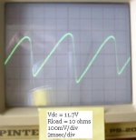
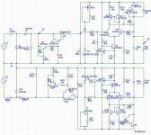
Hi, this is my last power supply version.
In the real life, the circuit need frecuency compensation by C8.
Vreg = Vzener*(1+R15/R16)
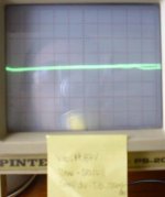
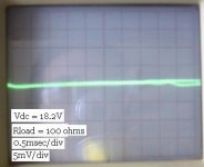
I take some pictures, with differents loads, 1k, 100, 50 and 10ohms.
Vdc was measuared with a simple voltimeter.
I think that the circuit work fine, any observation?
In the real life, the circuit need frecuency compensation by C8.
Vreg = Vzener*(1+R15/R16)
I take some pictures, with differents loads, 1k, 100, 50 and 10ohms.
Vdc was measuared with a simple voltimeter.
I think that the circuit work fine, any observation?
Attachments
Hi,
check Vce of the two mirror transistors and of the two LTP transistors. They do not look like they are matched in operating voltages.
What does a cap in parallel to R15 do for stability? I think it was GK that drew our attention to the problems that this extra cap causes.
Add a cap across the Zener D7. to reduce noise and give some improvement in AC performance.
Q5 sees 10k//15k on it's base. Q4 sees the Zener impedance on it's base.
Last edited:
Hi Andrew!Hi,
check Vce of the two mirror transistors and of the two LTP transistors. They do not look like they are matched in operating voltages.
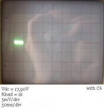
Vce(Q4) = 26,2V and Vce(Q5) = 26,5V with Vout = 17,90V
Ic(Q4) = 1,6mA and Ic(Q4) = 1,568mA
I will simulate in AC with a cap in parallel. Can I have problem with stability if the amplifier work in DC (compensed by C8)?What does a cap in parallel to R15 do for stability? I think it was GK that drew our attention to the problems that this extra cap causes.
ok, I will try with a cap, or a low pass filter. In what order is a Zener´s Vnoise? Some link with info maybe help me.Add a cap across the Zener D7. to reduce noise and give some improvement in AC performance.
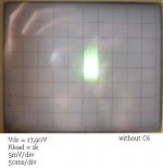
I put some pictures with and without C6.
Attachments
- Status
- This old topic is closed. If you want to reopen this topic, contact a moderator using the "Report Post" button.
- Home
- Amplifiers
- Power Supplies
- Discrete Regulator for VAS and Input Stage