Each capacitor is sized right to do the job. The 1st biggest cap is sized upon loading requirements and ripple voltage specs. Given the specs there are optimum solutions! If you need super big ones further on down stream for additional ripple filtering across the audio band, then you should consider using a regulator. Local supply decoupling needs to be sized correctly for its job too. Beware of using inductance in power filters as well, you need to take in consideration of ratio of C to L as well as damping.
If you don't understand the concept of small loop areas for EMI/RFI then you need to hit the books again.
If you don't understand the concept of small loop areas for EMI/RFI then you need to hit the books again.
Last edited:
Dear,
My experience is, that a first BIG cap, doesn't sound so good. A first small cap doesn't sound good either. Multiple same value small caps paralleled (preferable Panasonic FC) sound best in my subjective opinion. As well in low current applications as power amplifiers I prefer multiple small caps parallel. (e.g. for amplifier 40x 1000uF). We actually listen to different power supplies, same capacitance, 2 big caps vs. 40 small caps. The last one gave an amazing twist to the whole listening experience, in a positive way)
Commercial examples are, Classe audio, Sphinx, Gryphon audio.
Those solutions gives (subjectively again ) the most transparent low end, very deep resolution and a "fast" sounding listening experience.
I never like it to mix up different value caps in a system. e.g. sometimes u see designers use a 10000uF cap first followed by a 4700uF or lower value cap.
If you use multiple banks of small cap's the bandwidth is so high, that u only need local bypass cap's at the very end of the circuit.
Last but not least, choosing components is one, but the PCB layout is also drastic for sound quality. Often I see (line level) designs for pre-amps or active crossovers (means many opamps often) with the + and - PSU traces running separate all over the board and form huge loops. Stick all those differential pairs tight together, and only route them as pair everywhere and as much as possible. You will be surprised in sound quality.
In the DIY community we sometimes see designers go all over the top to both extreme extends. one side use way to small capacitance (come-one only 1000uF total for a power amplifier, is this realistic?) or we see on the other extend almost a Fahrad of capacitance in amplifiers. Both in my opinion are over de top. Use exact what you need for the application. Not more, not less.
With kind regards,
Bas
My experience is, that a first BIG cap, doesn't sound so good. A first small cap doesn't sound good either. Multiple same value small caps paralleled (preferable Panasonic FC) sound best in my subjective opinion. As well in low current applications as power amplifiers I prefer multiple small caps parallel. (e.g. for amplifier 40x 1000uF). We actually listen to different power supplies, same capacitance, 2 big caps vs. 40 small caps. The last one gave an amazing twist to the whole listening experience, in a positive way)
Commercial examples are, Classe audio, Sphinx, Gryphon audio.
Those solutions gives (subjectively again
) the most transparent low end, very deep resolution and a "fast" sounding listening experience. I never like it to mix up different value caps in a system. e.g. sometimes u see designers use a 10000uF cap first followed by a 4700uF or lower value cap.
If you use multiple banks of small cap's the bandwidth is so high, that u only need local bypass cap's at the very end of the circuit.
Last but not least, choosing components is one, but the PCB layout is also drastic for sound quality. Often I see (line level) designs for pre-amps or active crossovers (means many opamps often) with the + and - PSU traces running separate all over the board and form huge loops. Stick all those differential pairs tight together, and only route them as pair everywhere and as much as possible. You will be surprised in sound quality.
In the DIY community we sometimes see designers go all over the top to both extreme extends. one side use way to small capacitance (come-one only 1000uF total for a power amplifier, is this realistic?) or we see on the other extend almost a Fahrad of capacitance in amplifiers
. Both in my opinion are over de top. Use exact what you need for the application. Not more, not less.With kind regards,
Bas
Last edited:
The concept of paralleling many caps is from SMPS technology IE when the HF ripple exceeds the optimum ESR frequency for a single large case size, usually well beyond the audio band. So you must use a small case size to get the HF bandwidth first and then add more in parallel to reach the target ESR. The topology is still the same, large caps 1st.
Subjectively thru listening tests I have found that the larger the first cap the better sounding the bass became. But, the upper mid’s became “harder” sounding and more fatiguing. As of this date I am using a first cap about 50 percent larger than what is needed to keep the voltage up to peak charge, followed by multiple RC stages to get the ripple down to less than 10mv and a semi sine wave shape before it goes into the voltage regulator.
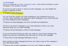
using PM generates this
infinia has chosen not to receive private messages or may not be allowed to receive private messages. Therefore you may not send your message to him/her.
It is really just a boost converter.Star,
could you start a new PSU thread and show us how?
Explain the operation of the circuit and from there take us through the design exercise to select components and values.
It can be links to other designs, not necessarily original.
http://www.onsemi.com/pub/Collateral/HBD853-D.PDF
Done with low voltages, it is a good way for the beginner to learn about power supplies without having to deal with the hazards of direct mains supplies.
If you don't mind the size and weight, it is also possible to build a passive PFC with just a large inductor. A junked microwave oven transformer can be easily rewound into a passive PFC inductor, or perhaps even be used as one as-is.
It can be links to other designs, not necessarily original.
Cirrus has recently announced a digital power factor corrector. Info here:
Digital Power Factor Correction (PFC)
I always avoid low ESR and big capacitors directly after the bridge since as people mentioned before, huge current peaks 100Hz or 120Hz which will introduce higher EMI.
I always use 300uH toroid coils after the rectifier bridge. Increasing the power factor slightly, reduces hum from the transformer itself, lowering the background electro smog noice inside the cirquit.
I have done scope measurements over a 0.01 ohm shunt with and without 360uH (from my big stock of surplus goodies) and the peak currents was reduced approx 40 times but only marginally affecting the output voltage.
Martin P
junk box parts, be careful you can make EMI worse using chokes not designed for the job esp unbalancing the normal cancellation you can get by simply twisting wires. Chokes for DC supplies need to be designed not to saturate and from re-radiating magnetic fields keeping coupling to other sensitive circuits to a minimum. Most people pay good money for transformers and low ESR caps to keep the regulation of an optimal circuit ( not over built from increased DC losses ). Watching current peaks is only a part of the EMI / RFI equations.
Good point Infinia, I use toroid chokes and they are rated at 10A dc. All buzz and hum just dissaperas in most amplifiers. By Bryston went dead quiet, even the main transformer went much quieter. Chokes in the power supply is a must!
Connecting bear can electrolytics directly on the rectifier is not recommended. If you cant find chokes you can add 0.33 Ohm resistors.
Martin P
Connecting bear can electrolytics directly on the rectifier is not recommended. If you cant find chokes you can add 0.33 Ohm resistors.
Martin P
Can someone please comment on the use of resistors in a crc powersupply design? Is this a good design for controlling ac noise? It seems a simple design. I guess there will be some voltage loss.Also ideal R values.
There seems to be a lot of different opinions what cap 1st. I wonder if anyone has tried small at the bridge then larger and small again at the output?
There seems to be a lot of different opinions what cap 1st. I wonder if anyone has tried small at the bridge then larger and small again at the output?
To achieve good ripple rejection it is simply high values of both the caps and the resistor that is most effective.
BUT!! Bear in mind that you will produce a lot of EMI (electro magnetic interfearence) with a high value of the cap1.
That is why i highly recommend a choke after the diodes and to avoid ringing insert a resistor in combination with the coil, with a voltage drop of 1% of output voltage.
So it should look like this (L+R) CRC or (L+R) CLC
Over each diode a 47nF capasitor can be parallelled to reduce EMI.
Martin P
when I repaired linear supplies for HF radios, generally manufacturers would use 1000 uF for 1 A drawn by the load (or 10000 uF for every 100 watts). another one was 3300 uF for 2.5 A . you would have to take into account load resistance for discharge time. as for chokes the bigger the better, 300 uh would be good for HF interference, but for low frequency rectifier noise 2-10 mH would be preferable. have same amount of iron in the choke as in the transformer!
Hi,
the first cap in a rCRC or rCLC has very high ripple imposed on it.
You must select a capacitor than can survive with this continuous ripple.
Either a very ripple rating cap or parallel a lot of smaller cheap capacitors.
I reckon the the last cap in the series most affects sound quality from the amplifier. Spend money on getting a good Audio Capacitor for this part of the PSU.
Based on my advice I come up with
r= resistance of transformer
C1= 1mF//1mF//1mF//1mF//1mF
R=1r0//1r0//1r0
C2=20mF for 8ohm speaker, or =40mF for 4ohm speaker.
Last edited:
- Status
- This old topic is closed. If you want to reopen this topic, contact a moderator using the "Report Post" button.
- Home
- Amplifiers
- Power Supplies
- First filter cap - Big or Small?