One thing that springs to mind when reading this thread:
Why is it always forgotten that the transformers used in these power supplies are not ideal? The winding resistance and leakage inductance dominates the charging cycle for all sensible configurations.
The dependence between capacitor value and conduction angle, and hence RMS/peak currents, is only significant when the source impedance is very low compared to the current drawn or for extremely low capacitance values.
Neglecting source impedance may be a good approximation (for relatively low power loads at least) when rectifying mains directly, but when using a transformer with a regulation of say 4% close to its rating it will yield results that are totally bogus. The difference in transformer steady-state RMS current if you select your capacitors for 10%, 1% or even 0.1% ripple voltage is not more than a percent if the load current is kept constant!
It is actually overly large transformers that should be fraught upon if you want to keep down peak currents during steady state operation! I'd better go hide now lest the audiophiles come hunt me down...
Adding a little extra inductance (or resistance) in strategic spots is an alternative though.
Why is it always forgotten that the transformers used in these power supplies are not ideal? The winding resistance and leakage inductance dominates the charging cycle for all sensible configurations.
The dependence between capacitor value and conduction angle, and hence RMS/peak currents, is only significant when the source impedance is very low compared to the current drawn or for extremely low capacitance values.
Neglecting source impedance may be a good approximation (for relatively low power loads at least) when rectifying mains directly, but when using a transformer with a regulation of say 4% close to its rating it will yield results that are totally bogus. The difference in transformer steady-state RMS current if you select your capacitors for 10%, 1% or even 0.1% ripple voltage is not more than a percent if the load current is kept constant!
It is actually overly large transformers that should be fraught upon if you want to keep down peak currents during steady state operation!
I'd better go hide now lest the audiophiles come hunt me down... Adding a little extra inductance (or resistance) in strategic spots is an alternative though.
I don't know of any general purpose aluminum electrolytic capacitors that aren't rated for line frequency rectifier duty.
The only possible reason you'd need high-ripple caps would be if you used a ridiculous amount of input capacitance, which as noted, results in absurd RMS currents, and is an all-around bad idea anyway.
The "2000uF/amp" rule of thumb must be qualified by ripple frequency and supply voltage. After all, you don't want to use 2000uF at 1kV, 1A, that's a seriously dangerous amount of energy! The correct value is:
C = 2.88 * Amps / (Volts * Frequency)
(Interesting, the 2.88 is dimensionless. If you include the units, it's farad-volt-hertz per ampere.)
So at 1A, 12V, 120Hz, you get:
C = 2.88 * 1A / (12V * 120Hz) = 0.002F = 2000uF
So the number is right.
A 6L6 PP amp might want around 400V and 200mA, or
C = 2.88 * 0.2A / (400V * 120Hz) = 12uF
Which is on the small side. Tube rectifiers can use somewhat more, because internal resistance keeps power factor high, at the expense of terrible regulation..
A really big switching power supply might need 160VDC at 10A, or
C = 2.88 * 10A / (160V * 120Hz) = 1500uF
A big audio amp might need +/-60V at 8A, or
C = 2.88 * 8A / (60V * 120Hz) = 3200uF
That's per side.
A TV flyback supply might need 30kV at 1mA, 15.7kHz, or
C = 2.88 * 0.001A / (30kV * 15.7kHz) = 6pF
Of course, this is limited by diode capacitance, which is comparable, and by allowable ripple, which is much smaller than 10%. Also, power factor isn't an issue for flyback supplies, because the current is constant. Large capacitances can be used at will. Picture tubes are on the order of 500pF, IIRC.
Tim
The only possible reason you'd need high-ripple caps would be if you used a ridiculous amount of input capacitance, which as noted, results in absurd RMS currents, and is an all-around bad idea anyway.
But it actually doesn't if there is a transformer.
The capacitor ripple current will not be higher than the transformer secondary RMS current, but can be a substantial percentage of it. The exact value depends on the conduction angle which in turn depends on transformer regulation and how close to full load you are.
Still, I'd agree 10% ripple is a pretty sensible value for most applications!
Last edited:
Power factor is the the ratio of the integrals I2t sin theta dt / I2t f(t)dt of the actual waveform. Essentially the ratio of the power which will produce a given amount of heat I2R in the supply conductor vs a sine wave driving a resistive load. So a load with a power factor of 0.1 would heat up the conductor the same as a load resistive load 10x greater. Integrating I squared Twith respect to time of the current waveform give the heating effect, it just happens be that plain reactive loads have a sinusoidal current draw and the integral of sine is cosine, that is why power factor is traditionally defined as cos theta.
But it actually doesn't if there is a transformer.
At constant load, if you increase the capacitance, you will monotonically reduce the power factor, regardless of the supply characteristics (ideal voltage source, transformer or otherwise).
The capacitor ripple current will not be higher than the transformer secondary RMS current, but can be a substantial percentage of it. The exact value depends on the conduction angle which in turn depends on transformer regulation and how close to full load you are.
Still, I'd agree 10% ripple is a pretty sensible value for most applications!
But it will be significantly higher than the DC output current, which is the only current that's doing any real work.
For instance, you simply cannot power a 1000W subwoofer amplifier (at full power) from a domestic 120V outlet without power factor correction!
Essentially all the RMS current from the source goes into the capacitor. A teeny bit remains as DC. If the transformer current is a square pulse of 10A for 1ms, every 10ms (a bad approximation, so what), it has an RMS of 3.16A and average of 1A. The cap sees -1A for 9ms and 9A for 1ms, or an RMS of 3.0A.
We can wave our hands and assert that, whatever the waveform really is, it has the same I^2*t as this pulse (for whatever conditions produced this). The capacitor RMS ripple current will always be slightly less than transformer RMS, but still very close.
It's my experience that the 2000uF/1A/12V/120Hz case gives a power factor around 0.5 at full load, and about 10% voltage ripple.
At constant load, if you increase the capacitance, you will monotonically reduce the power factor, regardless of the supply characteristics (ideal voltage source, transformer or otherwise).
Yes. But the difference between 10%, 1% or even 0.1% ripple is negligible if it is fed from a transformer with typical regulation values.
0.5 power factor sounds right for 10% ripple when the source impedance is negligible but if there is a typical amount of source impedance it should be closer to 0.7.
It's my experience that the 2000uF/1A/12V/120Hz case gives a power factor around 0.5 at full load, and about 10% voltage ripple.
What was the source impedance in that case?
Essentially all the RMS current from the source goes into the capacitor.
Let's see...
The output current only has a DC component and the capacitor current has no DC component. So in this case the RMS currents are related as Iin^2 = Icap^2 + Iout^2. The output RMS current is the same as the output average current because it's DC and the input RMS current is the form factor (of the input current) times the output current.
(Idc*K)^2 = Icap^2 + Idc^2
Icap = sqrt((Idc*K)^2 - Idc^2) = Idc * sqrt(K^2 - 1)
for a form factor of 1.8 which is a pretty typical value the capacitor RMS current will thus be 1.5 times the DC output current while the transformer current is 1.8 times the DC current.
If you have such low source impedance that you get 0.5 power factor the form factor is closer to 2.8 and in that case the capacitor ripple current is sqrt(2.8^2-1) = 2.6 times the DC current which is almost as much as the input RMS current and seems to fit well with your observation.
Another extreme is to put a large (infinitely large of course!) inductor between the bridge rectifier and capacitor and in that case the current drawn will be a square wave and consequently K=1 which leads to a Icap = sqrt(1^2 - 1)*Idc = 0A, as expected!
Last edited:
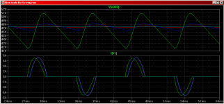
Here is a simulation of
a 36V 3A transformer with negligible leakage inductance and 10% regulation
a near-ideal bridge rectifier with 0V diode drop
an output capacitor that is stepped 1mF 5mF 20mF and finally 100mF
a load drawing 1.65A DC. The input current becomes 3.0A RMS for all four capacitor values. The capacitor ripple current is 2.5A RMS. Notice that the current waveform doesn't change much as the capacitor is stepped. This is because the voltage drop over the 1.2 ohm output resistance of the transformer is so much larger than the change in capacitor voltage.
which agrees well with the formulas from the previous post:
1.65A * 1.8 = 3.0A
1.65A * 1.5 = 2.5A.
The graph shows output voltage (top) and input current (bottom).
Attachments
Last edited:
Yup. Icap = Idc * sqrt(K^2 - 1) if the load for the first stage draws purely DC current, which should be a good approximation if you have a multiple stage filter. That's about 1.4 to 2.0 times the DC output current depending on how much resistance there is in the charging circuit before the first capacitor. It is never higher than the RMS current in the transformer secondary though for a purely DC load.
As ripple ratings go, I haven't seen an aluminum electrolytic which is not suitable for line frequency rectifier duty.
I feel like I'm repeating myself here...
There is no need to select a "high ripple" or "low ESR" type capacitor, "general purpose" is sufficient.
Something you probably won't use is a supercapacitor, which is not typically rated for this much ripple. The capacity would be way too high anyway, so this doesn't matter.
Tim
I don't know of any general purpose aluminum electrolytic capacitors that aren't rated for line frequency rectifier duty.
The only possible reason you'd need high-ripple caps would be if you used a ridiculous amount of input capacitance, which as noted, results in absurd RMS currents, and is an all-around bad idea anyway.
The "2000uF/amp" rule of thumb must be qualified by ripple frequency and supply voltage. After all, you don't want to use 2000uF at 1kV, 1A, that's a seriously dangerous amount of energy! The correct value is:
C = 2.88 * Amps / (Volts * Frequency)
(Interesting, the 2.88 is dimensionless. If you include the units, it's farad-volt-hertz per ampere.)
So at 1A, 12V, 120Hz, you get:
C = 2.88 * 1A / (12V * 120Hz) = 0.002F = 2000uF
So the number is right.
A 6L6 PP amp might want around 400V and 200mA, or
C = 2.88 * 0.2A / (400V * 120Hz) = 12uF
Which is on the small side. Tube rectifiers can use somewhat more, because internal resistance keeps power factor high, at the expense of terrible regulation..
A really big switching power supply might need 160VDC at 10A, or
C = 2.88 * 10A / (160V * 120Hz) = 1500uF
A big audio amp might need +/-60V at 8A, or
C = 2.88 * 8A / (60V * 120Hz) = 3200uF
That's per side.
A TV flyback supply might need 30kV at 1mA, 15.7kHz, or
C = 2.88 * 0.001A / (30kV * 15.7kHz) = 6pF
Of course, this is limited by diode capacitance, which is comparable, and by allowable ripple, which is much smaller than 10%. Also, power factor isn't an issue for flyback supplies, because the current is constant. Large capacitances can be used at will. Picture tubes are on the order of 500pF, IIRC.
Tim
This forumula produces values that to me seem completely contrary to the accepted rules of thumb. By my estimates, a 250W amp driving a 8R load would require ~70V rails, deliver 2.5Arms into the load and dissipate about ~1.7A (if biased into class A/B).
C = 2.88 * Amps / (Volts * Frequency)
C = 2.88 * (2.5A + 1.7A) / (70V * 50hz) // Australian 50hz mains
C = ~3500uF
How can 3500uF total filtering capacitance per rail possibly suffice in this case?
Last edited:
Yes. I don't know where the 2.88 comes from (it looks suspiciously exact!) but I think 10 would be a better figure - for 10% ripple. 20 would give 5% ripple. I would use peak signal current of 8A, and remember that a full-wave rectifier gives twice the ripple frequency.
Then C = 10 * 8A /( 70V * 100Hz ) = 11400uF
Then C = 10 * 8A /( 70V * 100Hz ) = 11400uF
Recently I have worked on similar problem, what should I put between rectifier and regulator. Spent a lot of time on scope, measuring ripple, currents, waveforms,....
Current draw 1A, only positive voltage needed, not too much voltage should be dropped before regulator. Arrived to DRLCRC solution.
Schottky diode - resistor - inductor - capacitor - resistor - capacitor
Current draw 1A, only positive voltage needed, not too much voltage should be dropped before regulator. Arrived to DRLCRC solution.
Schottky diode - resistor - inductor - capacitor - resistor - capacitor
Hmmmm...... looks like I've been sizing my first cap about right, according to this formula.Then C = 10 * 8A /( 70V * 100Hz ) = 11400uF
DF96 said:Then C = 10 * 8A /( 70V * 100Hz ) = 11400uF
My load is 1A at 5V, then
C = 10 * 1A / (5V * 100Hz) = 20000uF
According to this formula, 11400uF will suffice for 8A @ 70V.
And 20000uF is needed for 1A @ 5V.
And only 1000uF for 1A @ 100V.
Somehow I don't trust this formula.
Last edited:
Storm,
as you reduce the current drawn the required capacitance also reduces.
As you reduce the acceptable voltage ripple the required capacitance increases.
You must understand the software to enable you to assess if it is predicting the correct answers.
It comes back to my previous advice.
You must be able to check your results to ensure they are plausible.
- Status
- This old topic is closed. If you want to reopen this topic, contact a moderator using the "Report Post" button.
- Home
- Amplifiers
- Power Supplies
- First filter cap - Big or Small?