My phono amp is using 2 Plitron transformers for independant L & R supply. The consumption is 300mA on each rail. The original spec as printed on the transformer is 44V 1.5A on each supply and therefore I have ordered my new transformer (using OCC silver plated wire as secondary winding) at 44V 1A. With loading, the original Plitron is 46.5V but the new transformer is only 45.8V.
The sonic difference between the 2 transformers is very significant. The new transformer has very musical high, more details but the bass is not as punchy as the original Plitron; although not very much.
I can return my new new transformers to the manufacturer and increase the secondary voltage to 46V that I believe it will produce a higher AC voltage with loading. I have the following questions: -
1. Why a loading of 300mA can reduce the voltage between these 2 transformers, bearing in mind the new transformer is already at 1A per rail?
2. The transformer manufacturer can either rewind the entire secondary of the transformer or solder a new wire and add more rounds but the price difference is high. Will the cheaper second method reduce the performance of the transformer?
3. The manufacturer said I can send my original Plitrons to him and he will rewind it with OCC silver plated wires that he said it will even be better. Could this be true?
Last edited:
Hi SunSun, the nominal voltage of the transformer is at full load, as the two transformers have different VA ratings (the first is 66VA and the second is 44VA) they almost certainly also have different regulation (the regulation figure will tell you what the max voltage will be above the nominal voltage, assuming no load). Even with regulation put asside, at 300ma on the first transformer you are only using 20% of the available current for the transformer therefore the voltage drop will probably be less than for the second one where you are drawingt 30% of the available current. If you have the regulation figures for each transformer you should be able to calculate it ")
I will pass on attempting to answer 2 and 3
Tony.
I will pass on attempting to answer 2 and 3
Tony.
Thanks Wintermute. I have another thinking -
The primary of the new transformer is 220V. I have an isolation transformer that is 220V primary but selectable secondary at 220/230/240V. If I choose 230V output; which is about 4.5% more. I think this will give a boost of secondary AC output by 2V. Could this hurt the primary windings? Is this an option?
The primary of the new transformer is 220V. I have an isolation transformer that is 220V primary but selectable secondary at 220/230/240V. If I choose 230V output; which is about 4.5% more. I think this will give a boost of secondary AC output by 2V. Could this hurt the primary windings? Is this an option?
Thanks Wintermute. I have another thinking -
The primary of the new transformer is 220V. I have an isolation transformer that is 220V primary but selectable secondary at 220/230/240V. If I choose 230V output; which is about 4.5% more. I think this will give a boost of secondary AC output by 2V. Could this hurt the primary windings? Is this an option?
It will work but I wonder if it is worth the effort and worry and money. A difference of 0.7V at around 45V is 1.5%. That 1.5% translates to a difference in max output level before clipping of your amp of 0.13dB.
I would be very happy the way it is!
jd
I think I have to give a full picture on my application.
The AC output from transformer will go through a LC filter then to a shunt regulator for 24V regulated output. The shunt regulator; as stated in the manual, needs 5V difference to work properly.
In the original setup, the 47.5V AC output produces 28.8V DC after LC filter which is already very marginal for the required voltage drop. It will then go through the shunt regulator for 24V DC output. Using the new transformer only produces 45.8V AC reducing the voltage before shunt to 26.7V - that is only 2.7V voltage difference left behind.
The new OCC silver plated wire transformer produces very good highs and details but the bass is not as good as the original transformer. I "think" it will be better if I can lift the input voltage to shunt regulator to 29V.
1. Is my "think" valid?
2. I have another though - place a resistor in parallel with the choke to reduce the internal resistance therefore giving a higher voltage before regulation. Is this another option?
3. Rewinding the secondary by soldering a new section of wire to the existing wire only costs me a small amount of money but would this reduce the performance of the transformer? Of course, another option is to rewind the secondary totally but the cost is about 2/3 of the original cost.
Thanks
Can you post your schematic and any measurements. something does not compute.
47.5 V ( 1/2 ?) *1.41 ~ 33.5 Vdc (or 32 Vdc on the new XFMR) ! Consider using a CLC instead of a LC.
Is it possible for you to lower the regulator output voltage a bit to acheive the optimum headroom and keep power loss lower?
You speak about silver wire on a PS transformer as if the music it self travels through this basic component?
Last edited:
yes please post the schematic, and also the DCR of your colis! I'd expect somewhere in the vicinity of 63V (no load) rectified from a 45V ac source with nothing other than caps after the rectifier, so to be getting only 28.8V, over 30V is disappearing somewhere, or the setup is not as I am envisaging
Tony.
Tony.
Yes, I also use Duncan Amps Tools and do some simulation by changing the filter from LC to CLC and it will give much higher voltage. The original circuit uses LC filter therefore I just follow it. What are the differences between LC and CLC other than the higher DC voltage output?
rC, rCRC, rCLC all operate as a capacitor input filter. On zero load current, the capacitors charge to the peak of the sine waveform less some rectifier diode drop.
An LC or LCLC or LCRC all operate as a choke regulated supply.
The upper and lower limits of current are defined by component value choices.
If the current goes outside the range for choke regulated then it starts operating as a capacitor input filter. In this low current condition the output voltage rises from ~0.9*Vac to ~1.4*Vac.
LC supplies cannot be used for circuits that demand a big change in current.
The consumption is designed on constant current draw at 264mA. Since it is on constant current draw, I also wonder why do I need such a heavy duty power supply and regulator.
I put a 220 ohms 2W resistors across the choke (in parallel) and the voltage output before the regulator becomes to 30V. The bass returns with very clear and punchy result. The overall performance of the power supply changes my system completely although I can only listen to it for a few minutes.
There is a minor problem with the resistor. I measured the voltage drop across the resistor (in parallel with the choke) is 10.6V but it is burning hot. My calculation as follows: -
V=IR, 10.6=I*39.2, I = 270mA (39.2=1/(1/47.7 (choke's R) + 1/220)
W=I^2R, .27^2*39.2 = 2.87W
I don't know how to distribute the W between the choke (47.7 ohm) and the 220R. If I use inverse proportion, the R is only having somewhere around 0.8W but why is it so hot (I can't touch it after 2 minutes)?
Last edited:
Well, 270mA is the current that the AMP is biased to, right? You forgot that linear regulators work by converting excess energy to heat. Maximum theoretical efficiency is 50%, and in the real world you'll be lucky to get 30%. The higher the voltage difference between the input and output, the more heat dissipated, the less efficiency. I think you can figure that out already.
I wouldn't be surprised if you're actually drawing in excess of 1A from that transformer. The only way to find out for sure is to meter it.
I wouldn't be surprised if you're actually drawing in excess of 1A from that transformer. The only way to find out for sure is to meter it.
10.6V voltage drop is metered on the choke (in parallel with the resistor) therefore it should be the consumption from the transformer's secondary winding. If we have to put efficiency into the picture, it will be the primary of the transformer that we have to take into account. Therefore
270mA x 46.5V (on the secondary) = 220V x 57mA x efficiency (on the primary)
Is this correct?
270mA x 46.5V (on the secondary) = 220V x 57mA x efficiency (on the primary)
Is this correct?
10.6V voltage drop is metered on the choke (in parallel with the resistor) therefore it should be the consumption from the transformer's secondary winding. If we have to put efficiency into the picture, it will be the primary of the transformer that we have to take into account. Therefore
270mA x 46.5V (on the secondary) = 220V x 57mA x efficiency (on the primary)
Is this correct?
The voltage across the choke is in fact the ripple plus the DC difference. So the voltage across the R is more than it appears.
But there's another issue. You size this supply for the amp bias of some 300mA. But when you draw power from the amp that current goes up much higher. So you better have a large cap after the lin reg to sypply those bursts, and make sure the reg can source more than 300mA!
There's your impact on the bass: bass notes take larger currents for larger periods so the supply voltage collapses if you have a wimpy reg.
What's the expected power this amp should deliver into 8 ohms?
jd
The power supply and amp design is from Germany. The cap after the L is already 10,000uF that; again, I "think" is more than sufficient. I also used Duncan Amp Tools to simulate and the result shows the ripple current is very low. Is there other method to determine if 10,000uF is sufficient?
Power supply detail as follows
44V (full load) 1.5A
L is 5H 47.7 ohms
capacitor is 10,000uF 63V (Jensen 4 poles) with 2.2K
Power supply detail as follows
44V (full load) 1.5A
L is 5H 47.7 ohms
capacitor is 10,000uF 63V (Jensen 4 poles) with 2.2K
Last edited:
The voltage across the choke is in fact the ripple plus the DC difference. So the voltage across the R is more than it appears.
But there's another issue. You size this supply for the amp bias of some 300mA. But when you draw power from the amp that current goes up much higher. So you better have a large cap after the lin reg to sypply those bursts, and make sure the reg can source more than 300mA!
There's your impact on the bass: bass notes take larger currents for larger periods so the supply voltage collapses if you have a wimpy reg.
What's the expected power this amp should deliver into 8 ohms?
jd
This is a class A phono pre-amplifier being discussed here, not a power amplifier.
A schematic would be helpful. The DCR of your chokes is quite high for the voltage used and the current required, are you using the DCR of the choke in conjunction with the shunt regulator or do you have a CCS or current limiting resistor in series with the supply?
Ideally if you need bipolar 29VDC out of a choke input supply this implies something like two 30Vrms windings on your transformer or a 60VCT transformer. You can perhaps simulate this by adding some additional AC with small transformers connected in series to boost the AC output voltage by 5V or so.. Once you know the target voltage you can get a new transformer built.
IMHO I think the difference you are hearing between the two transformers has more to do with the degree to which the shunt regulator is unhappy due to insufficient input voltage margin for it to achieve full regulation and a low output impedance. Through that choke input filter you should not be able to "hear" the transformer at all. IMHO this is a huge waste of money or something else is seriously wrong with this design..
well we are all guessing (still) without a schematic.The cap after the L is already 10,000uF that; again, I "think" is more than sufficient. I also used Duncan Amp Tools to simulate and the result shows the ripple current is very low. Is there other method to determine if 10,000uF is sufficient?
Yes the charging current is low, if that's the goal, but it's RLC time constant is too large to charge up to the proper voltage. If you split the very large cap in two, forming a CLC the charging current in the last cap should be even lower yet providing enough voltage. Is there a problem with this aproach?
LTspice should model the thing, but the question is, what is the design trying to achieve. What parameter is driving the requirement for an inductor fed charging current. Low output Vripple is usually the goal for normal supplies. With careful layout management by keeping a small loop area for charging the first input cap, you should have most excellent ripple performance. Good voltage regulators should have an additional 70 dB of rejection, knocking the resultant output ripple into the noise.
I simulated CLC but the output voltage is around 41V which is too high. I can play around with the first capacitor to reduce the output voltage but I really want to know if CLC is producing a higher output voltage, why the designer uses a LC design?
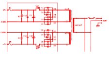
Design spec:
Transformer 44-45V (full load) 1.5A
L 5H 50ohms
C 10,000uF 63V
R 2.2K 5W
I also added a 0.1uF at the output across the C
After the power supply, there is a shunt regulator for constant current draw at 264mA (actual shows 270mA) to supply a phono amp designed to draw 200mA. I can reduce the CCS to 240mA (the minimum recommended CCS) that can help to increase the power supply output by 0.x volt.
Attachments
Last edited:
When I placed a 220R across the L, it produces adequate voltage to the regulator. I just measured the current flow across the 220R, it shows 48mA. In this respect, the power is only around 0.5W but the resistor with a rating of 2W (Kiwame 2W) turns burning hot (over 100 degree C after 1.5 minutes). Why could this happen? Is over 100 degree C normal for resistor?
- Status
- This old topic is closed. If you want to reopen this topic, contact a moderator using the "Report Post" button.
- Home
- Amplifiers
- Power Supplies
- Why voltage dropped in my new transformer?