Hello
This is my first post! Just finished my a levels on Tuesday!
I'm hoping to go to Swansea uni to do electronical engineering in September.
I was given this for Christmas but have yet to get it working i am unsure about the power supply.
Velleman nv
On the website they recomend a
TOROIDAL TRANSFORMER 120VA 2 x 30V / 2 x 2.00A
Velleman nv
Is there a cheaper option/ beter option and how should i connect it all up to my UK main supply?
Thanks Llyr
since your theory is kinda fresh ...use the things you have learned and come up with the answer to the question """how come a 120VA transformer will ever produce sound of 200W ?? """
your amplifier is over estimated and will only produce arround 50-60 watts per chanel ...so 120VA trafo is not even enough for good operation in 8 ohms and the minimum should be to have one per chanel ...
it will work with less or it could still play decent with one trafo for 2 chanels but dont expect full power without distortion or full power with 4 ohms loads
on the other hand your output transistors cannot safely operate at 4ohms full power ...
be careful how to set idle and most importand the pargraph that says about how and which transitors need to be screwd on the heatsink
you cannot operate this amp without heat sink not ven for a test not even for a second
regrads and welcome sakis
Okay thanks. Yeah i did guess it would not output 200W
It's says on the website
# 100Wrms power @ 4 ohm load
# 70Wrms power @ 8 ohm load
But you think only 50-60?
Its only know i found out 120VA means 120V at 1A.
I have only got on channel. And Ive found a good heat sink to use.
It's says on the website
# 100Wrms power @ 4 ohm load
# 70Wrms power @ 8 ohm load
But you think only 50-60?
Its only know i found out 120VA means 120V at 1A.
I have only got on channel. And Ive found a good heat sink to use.
You may check :
Velleman 70W universal power supply - low profile model
Velleman 70W universal power supply - regular model
Those are 70 watt universal switched mode power supplies, working from 100 VAC to 240 VAC.
Check if your Velleman amp is designed for operating from a +24 VDC / -24 VDC supply, and check what is the (reduced) output power when fed with such voltage.
Start using your amp this way during one week, on a +24 VDC and -24 VDC supply, use and abuse it, and measure the output power before clipping or distorting on 8 ohm, 4 ohm and 2 ohm, at 1 kHz and at 20 Hz.
For measuring the distorsion, you may use Audiotester 3 : audioTester
If the output power at 20 Hz is much less than the output power at 1 kHz, you may add some extra capacitance, external but as close as possible to the outputs of the supplies. Try with 10,000 microfarads / 50 Volt. Add another 10,000 microfarads / 50 Volt if needed. Per supply.
Use and abuse your amp during one week. You may enjoy the extra headroom the 10,000 µF capacitor provide in the deep bass range.
If you have some money left, buy two spare supplies, the same you already use, and start this project :
Open the Velleman power supplies
Reverse-engineer them
Do some surgery inside for boosting the output voltage to 32 VDC :
- locate the electrolytic output capacitor and check if he can sustand 32 VDC
- locate the DC feedback network and adapt it for generating 32 VDC instead of 24 VDC
- locate the internal 12V supply (used to power the controller IC and MOSFET gate) and check if it feels happy when the secondary of the transformer is delivering 32 VDC at the output instead of 24 VDC at the output - an oscilloscope is needed for understanding the changes - BE VERY CAREFULL when doing this because what you think to be the ground of the controller IC, is NOT the ground, but is at MAINS POTENTIAL : LETHAL DANGER - this is why I'm asking you to reverse-engineer the whole circuit before putting your fingers on it.
Get your work published in Elektor early 2011. This will be the logical continuation of the article published in June 2010 : "Alternative HiFi power supplies".
Alternative HiFi power supplies - ELEKTOR.com | Electronics: Microcontrollers Embedded Audio Digital Analogue Test Measurement
If you survive this, you may step to the 150 watt universal switched mode power supplies, working from 100 VAC to 240 VAC, do the same trick, this time replacing the output electrolytic capacitor by a 50 volt model, and set the output voltage to 42 volt.
Velleman 150W universal power supply - regular model
Now your Velleman amp will deliver the max power, 20 Hz to 20 kHz.
If you feel happy, using and abusing your amp, you may design your own twin 150 watt (= 300 watt) symmetric +42VDC -42VDC audio power supply, dismantling the components of the Velleman units, and soldering them back on a custom-PCB that you will have designed. Add some features diyAudio freaks may love :
- syncking the two units (that's easy but tricky due to the earth potential difference : use an optocoupler to define a master unit synching a slave unit)
- tweak the feedback network in such a way that the two outputs remain the same in absolute value - if one unit gets overloaded and reduces its output, then the other unit would follow for avoiding the amp to be fed by an assymetric voltage (this would be much appreciated).
- introduce the concept of redundancy, paralleling inexpensive 70 watt supplies, low height : if you parallel 2 units, you get twice the power and more reliability.
- introduce the concept of syncked and interleaved redundancy, paralleling inexpensive 70 watt supplies that are syncked and phase shifted in such a way that the output ripple gets minimized (this would be much appreciated)
Get your work published in Elektor somewhere in the middle of 2011.
For letting you become an expert in switched mode power supplies for audio, do the same, around June 2011, basing on the ON Semi NCP1651 "Single Stage Power Factor Controller". Datasheet here : ON Semiconductor NCP1651: Single Stage Power Factor Controller
If you hit the 120 watt barrier with the ON Semi NCP1651, you may introduce the concept of syncked and interleaved redundancy, paralleling inexpensive 120 watt supplies that are syncked and phase shifted in such a way that the output ripple gets minimized. This may add value to the ON Semi NCP1651 chip.
At this stage, dealing with power factor controllers in audio power supplies, if you need specific magnetics for the NCP1651 controller, you may contact j.turchi@onsemi.com
You may reply this is a very complicated way to get a power supply for an audio amplifier. I will reply this is the best way for you to become an expert in switched power supplies, power factor controllers, meet international people, get your work published & have a lot of fun.
To the people replying to you using internet, that may say that a switch-mode power supply for an audio amp is a bad idea, tell them that even the typewriters (= computers) they are using to reply, are using at least two switch-mode power supply inside, and that their message got conveyed through hundreds of routers and network appliances, all being fed by switch-mode power supplies. On top of this, with the advent of class D power amplifiers, it will be viewed like madness, having a class D power amplifier powered by anything else than a switch-mode power supply. So, be assured that putting your eyes and fingers in switch-mode power supplies for audio, surviving the electrocution danger, and coming with something efficient and respectfull for the grid (thanks to the power factor control feature) is a gold pass for your future.
"Just do it"
Last edited:
This amplifier won't deliver a continious 200W, but I suggest you take a >300VA transformer. You should take capacitors with a high capacitance like steph said before.
This power supply will work well.
This power supply will work well.
An externally hosted image should be here but it was not working when we last tested it.
Last edited:
Please be very carefull when "playing" with it. Are you planning opening it and tweaking it ? Remember, you need two switched mode power supplies put in series for generating +24VDC and -24VDC. Feel free to ask in case of need. There are no stupid questions. I'll help you.Thanks alot!
I will look into using the switched mode power supplie I think i have a similar universal one around the house to have a play with!
P.S.
I saw your other post, your A level electronics project bass amp. Nice & clean picture. Nice & clean diagram. If you start a new thread entitled "my A level electronics project bass amp", I'll help you simulating and analyzing it using LTspiceIV. If you want. Same for the Velleman amp. We can simulate and analyze it using LTspiceIV.
A 2x30V transformer produces approx +/-40V to +/-45V rails after rectification and smoothing, which are just under the limit for TIP127/TIP147 darlingtons working at 4 ohm.
These rails (and the SOA of TIP127/TIP147) allow to get close to 200W at 4 ohms, but not in a sustained way, just in an intermittent way, as required by music signals.
A 120VA transformer is good for two "200W" channels for the same reason, music never demands full power continuously for more than a few miliseconds. Thus, average power consumption of two "200W" amplifiers playing music just below the volume level where distortion (clipping) starts is not likely to exceed 100W (although each module may be drawing up to 400W during a fraction of a second, yes, peak power in a sinewave is twice the average power).
Designing amplifiers to be able to provide full power continuosly is unrealistic. It results in bulkier amplifiers costing and weighting 2-5 times more than the ones designed with common sense and music signals in mind.
On the other hand, music performance is the same, the extra power capability they are paying for (and carrying on their backs) is never used when playing music, it can be only used during bench testing.
Last edited:
Hmmm.........
some people are clueless .......
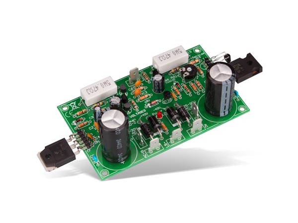
That amplifier board has the rectifiers and supply capacitors fitted.
As such the board has AC connections for a mains transformer.
120VA does not mean 120V at 1A only, here it usefully means
0.5A at 240V for the maximum primary current and also max 2A
for a 30V-0-30V AC secondary.
That it what you need, and Maplin sell one for £26, N26JB.
Needless to say, don't build mains powered equipment if
you don't know how to do it properly, it is dangerous.
If you electrocute someone, it will get you in a lot of trouble.
I don't know what you intend to use a mono amplifier for ...
rgds, sreten.
Personally I'd use this or similar :
http://cpc.farnell.com/multicomp/mcfe120-25/transformer-120va-2-x-25v/dp/TF01406
some people are clueless .......
That amplifier board has the rectifiers and supply capacitors fitted.
As such the board has AC connections for a mains transformer.
120VA does not mean 120V at 1A only, here it usefully means
0.5A at 240V for the maximum primary current and also max 2A
for a 30V-0-30V AC secondary.
That it what you need, and Maplin sell one for £26, N26JB.
Needless to say, don't build mains powered equipment if
you don't know how to do it properly, it is dangerous.
If you electrocute someone, it will get you in a lot of trouble.
I don't know what you intend to use a mono amplifier for ...
rgds, sreten.
Personally I'd use this or similar :
http://cpc.farnell.com/multicomp/mcfe120-25/transformer-120va-2-x-25v/dp/TF01406
An externally hosted image should be here but it was not working when we last tested it.
Last edited:
tnx for the enlightment, can you help me how to know the actual amp. rating value counterpart between torroidal and ei transformer eg. what will be the counterpart for 160va torroid.., would it be 6amp ei transformer? coz torroidal are hard to obtain or to expensive here in the philippines
Hi,
The transformer rating depends on what rail voltages you use and
that depends to an extent on the efficiency of the heatsinking fitted.
I'd fit around 100VA, toroidal or EI. For reliability I'd run it off 25-0-25VAC.
But up 30-0-30V is possible, for 8 ohms, 25-0-25V for 4 ohms IMO.
rgds, sreten.
Its a case of RTFM : http://www.vellemanprojects.eu/downloads/0/modules/usermanual_vm100_rev1.pdf
Most probably, you have gotten this manual with the kit:
http://www.velleman.eu/downloads/0/illustrated/illustrated_assembly_manual_k8060_rev1.pdf
If the info in this manual is insufficient for you to hook up the transformer, then please, do not continue your work on this amplifier without the direct help of someone who knows what he or she is doing. And forget everything that has been said in this thread about alternative power supplies for the time being, just stick with the manufacturer's recommendation. Velleman indicates a level 5 for this kit, their most advanced level. Considering this, the nature of your questions worries me a bit...
- Status
- This old topic is closed. If you want to reopen this topic, contact a moderator using the "Report Post" button.
- Home
- Amplifiers
- Power Supplies
- Velleman 200W amp