Hey all,
Since communication between me and Bora has slowed to a mysterious halt, I assume that I will need to ask my questions here for the time being.
I need plenty of help to get though my lack of knowledge of electronic theory.
I need to make sure that the out put with be +/- 36volts, and I'm unsure what alterations i will need to make in order to achieve this. Also what kind of transformer would i need to get this...
I also want to add some sort of LED to show that the power-supply is on.
I also don't know anything about selecting a proper 24volt relay, or choosing the values for that relay... (Talking about the two resistors with an asterisk and the capacitor)
I would also like, if possible, to have a +/-12volt rail for a "lightspeed"
Sorry for all the questions,
Kurtis
PS. the attachments go in-order from left to right
1. My assumed calculations, as well as a thyristor that i think would work
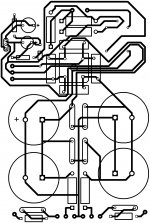
2. Board layout, beta stage, plenty of scale problems
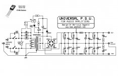
3. original unchanged schematic
Since communication between me and Bora has slowed to a mysterious halt, I assume that I will need to ask my questions here for the time being.
I need plenty of help to get though my lack of knowledge of electronic theory.
I need to make sure that the out put with be +/- 36volts, and I'm unsure what alterations i will need to make in order to achieve this. Also what kind of transformer would i need to get this...
I also want to add some sort of LED to show that the power-supply is on.
I also don't know anything about selecting a proper 24volt relay, or choosing the values for that relay... (Talking about the two resistors with an asterisk and the capacitor)
I would also like, if possible, to have a +/-12volt rail for a "lightspeed"
Sorry for all the questions,
Kurtis
PS. the attachments go in-order from left to right
1. My assumed calculations, as well as a thyristor that i think would work
2. Board layout, beta stage, plenty of scale problems
3. original unchanged schematic
Attachments
I don't really get it. You can get any voltage by scaling the transformer output voltage. The relay is overkill for a soft start; there are other ways. A simple lamp connected across any transformer winding will indicate power on. If you insist on using an LED just compute the required series resistor, and run it from a dc output.
I don't know what a lightspeed is. How much current do you need for it? That is all important regarding what sort of circuit you need to obtain the 12V.
I don't know what a lightspeed is. How much current do you need for it? That is all important regarding what sort of circuit you need to obtain the 12V.
Thank's for your help so far
This is a lightspeed: DIY "Lightspeed Attenuator" - Passive LDR Volume Control (audio optocouplers)
Regards,
Kurtis
This is a lightspeed: DIY "Lightspeed Attenuator" - Passive LDR Volume Control (audio optocouplers)
Regards,
Kurtis
Both of the supplies in the attached pictures are totally inappropriate for a Lightspeed passive preamp. All the Lightspeed needs is a low power single supply.
I you are inexperienced with electronics, I would use a 'wall wart' power supply Use one outputting around 10 to 20VDC, and use the LM7805 circuit in the link you posted. You should be able to find one lying around, from an old computer router or similar.
I you are inexperienced with electronics, I would use a 'wall wart' power supply Use one outputting around 10 to 20VDC, and use the LM7805 circuit in the link you posted. You should be able to find one lying around, from an old computer router or similar.
You can use a simple divider or transistor regulator off the positive supply to get the voltage you need. Frankly, after reading the hype on lightspeed, I am not impressed with its design. It's too complicated and draws too much current.
But who am I to interfere with a legend, which this seems to have become.
But who am I to interfere with a legend, which this seems to have become.
Sorry, I missed the bit about you adding the supply for the Lightspeed to the PSUs you posted. I assume you're building some sort of integrated amp.
The simple circuit I've attached will work, you only need a single 5VDC supply for the Lightspeed.
Don't use the board layout you posted, it's a shocker. Do a bit more research on how PCBs are best laid out before you attempt something like that.
The simple circuit I've attached will work, you only need a single 5VDC supply for the Lightspeed.
Don't use the board layout you posted, it's a shocker. Do a bit more research on how PCBs are best laid out before you attempt something like that.
Sorry, I missed the bit about you adding the supply for the Lightspeed to the PSUs you posted. I assume you're building some sort of integrated amp.
The simple circuit I've attached will work, you only need a single 5VDC supply for the Lightspeed.
Don't use the board layout you posted, it's a shocker. Do a bit more research on how PCBs are best laid out before you attempt something like that.
I don't think you've attached anything to your post.
I'm not making anykind of integrated amp, I'm currently making Carlos's Blame ST
I'll spend some time researching PCB's too
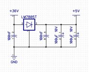
That regulator circuit is only good for very low load current, as the 31 Volts across it can cook the chip if the current is high enough. I was thinking to offer that but didn't try to calculate the required load current, or even verify that the chip can handle that high an input voltage. A series resistor at its input might be a good idea.
Here's the picture I meant to attach. If it's not an integrated amp, what's the +/- 36V for?
For the +36volt rail and the -36volt rail of the powersupply are for a discrete class A poweramplifyer (Blame ST). The +/-36volts is an estimate of what will happen if i drop the secondary voltage of the transformer by six volts from the original schematic (Was +/-42volts). I have no clue if this will even work. And i still need to set the values of the two resistors and capasitor in the relay circuit, which might I add, can't be done untell I know for certan what the VAC of the secondary side needs to be inorder to get the 36volts on the rails for the Blame ST.
If i drop the voltage to 24volts (from 30volts) on the primary side of transformer and stick a second 1N4007 before the rectifier(Which connects to the Voltage regulator). Then the LM7805T will only need to regulate 24volts, right? I think the Lightspeed will be pulling less then 1 amp.
I would like to create some sort of alterd schematic from the original schematic so that I can doccument the changes. Starting will removing the six 1N4007 leading to the 56volt rails.
Thanks for all your help so far!
Kurtis
- Status
- This old topic is closed. If you want to reopen this topic, contact a moderator using the "Report Post" button.
- Home
- Amplifiers
- Power Supplies
- Modifying Powersupply