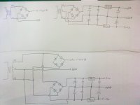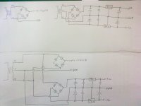
Actually i want to combine this two circuit(above part) by using only one center tap transformer. At the beginning i'm using two type of transformers but now i want to combine it to become using one type of transformer to save down one transformer. So instead of using one 24-0 and one 12-0-12 transformer i combine it together by just using one 24-0-24 center tap transformer as shown at the bottom part.
Does my circuit correct to get the final output voltage as the upper part?
thank you
a single secondary cannot easily give a dual polarity supply.
A dual secondary or a centre tapped secondary both give a dual polarity supply.
The 24-0-24Vac could give a very high voltage at the smoothing caps, maybe as high as +-40Vdc.
This may overload the 7x12 regulators.
A dual secondary or a centre tapped secondary both give a dual polarity supply.
The 24-0-24Vac could give a very high voltage at the smoothing caps, maybe as high as +-40Vdc.
This may overload the 7x12 regulators.
centre tapped secondary of 24-0-24Vac as you have proposed.
Take a dual polarity supply from the main PSU and drop the voltage using a tracking pre-regulator based on an LM317 (+ve) and LM337 (-ve).
This pre regulator arranges for the next series regulator (LM78xx & 79xx) to always see an adequate voltage to never drop out while good mains is available and the tracking part ensures that the series regulator never sees a voltage at it's input that is greater than maximum rating.
That's a total of just 4off 3pin regulator ICs.
hi,
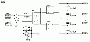
As i refer to Power Supply for Power Amplifiers

My connection is almost same as his design to have dual power supply. So can my circuit works?

thank you.
As i refer to Power Supply for Power Amplifiers

My connection is almost same as his design to have dual power supply. So can my circuit works?

thank you.
It will work fine. (Although two diodes in the upper bridge do not serve any useful purpose and can be omitted.)
thanks for the reply.
So as refer to the paper i posted up.the left upper part output to my circuit A. I just wonder that,does the circuit at the bottom part which also output to the circuit A has the same output voltage as the upper part? Because i had change the transformer from a 24-0 to a 24-0-24 and the connection has changed too.
thank you.
It took me awhile to figure out that in the second drawing the bridge to circuit "A" is not a bridge, it's just two diodes.
yea. actually i should avoid the two diodes.
thanks.
Hi Motbuddy,
I'm trying to build the exact same circuit as yours. I want to have 3 voltages: +5V, +12V and -12V. I'm doing the first design like yours. I want to use 2 transformers as I can use a lower voltage one for the +5V supply so that I don't have to dissipate so much heat with the regulator on this rail. I need 2.6A on the +5V rail.
What I concerned is the ground. There are two separate grounds on the two circuits, one using the center tap from the +/-12V circuit, the other one is not using center tap as ground. Would the two circuits work together by connecting the two different grounds together?
Hi,
you use the word circuits.
A circuit is a circular type loop. What goes out in the flow must come back in the return. If it can't it's not a circuit.
Can the two circuits operate correctly if they are completely independent. Or asked another way, do the circuits need to be connected together for the two circuits to operate?
Hi,
you use the word circuits.
A circuit is a circular type loop. What goes out in the flow must come back in the return. If it can't it's not a circuit.
Can the two circuits operate correctly if they are completely independent. Or asked another way, do the circuits need to be connected together for the two circuits to operate?
Of course I know the 2 circuits will work independently.
I mean I want to use both circuits if (ground) connected together. The device I'm powering requires all 3 voltages (+5, +12, -12) simultaneously.
If not, can I use a center tapped transformer in the top circuit, and use a dual half wave rectification (2 diodes), so both circuit grounds are connected to the CT in each separate transformer?
will the two circuits work independently?I want to use 2 transformers ................. Would the two circuits work together by connecting the two different grounds together?
then why do you need to connect them together?I know the 2 circuits will work independently.
The two transformers will create two isolated supplies that can power two isolated circuits. They don't need to be connected together.
I guess I've not been too clear. The word "circuit" refer to the two rectifying circuits in this topic. The device I'm powering is actually just one physical circuit, which requires +5, +12 and -12V.
My device was powered by a SMPS and I want to change it to Linear PS. But I want to minimize power dissipation on the 5V rail so I use a transformer with 7VAC secondary. Now I've two linear power supplies, one providing 5V and the other providing +/-12V DC. Can I physically connect both supplies to my device as I noticed that the +/-12V one has ground in the CT of the transformer, but the +5V one has ground on one end of the transformer's secondary. The two "grounds" are not in phase during an AC cycle.
What I worry is that these two grounds may have different potential...
BTW, I have the parts, but the supplies have not been built yet.
the two transformers and their PSU each give an isolated output flow and return.
The 12V version could be 0,12,24Vdc or 0,-12,-24Vdc or 12,0,-12Vdc or any other combination that covers a range of 24V,i.e. 100,112,124Vdc.
The 5V version could be 0,5Vdc, or 0,-5Vdc, or 12,17Vdc, etc
If you link any ONE output from the 12 to any ONE output from the 5 then you will have one common voltage and the three other voltages.
I cannot tell you if the 4 power input terminals are designed to work well together with a common 0Vdc.
the two transformers and their PSU each give an isolated output flow and return.
The 12V version could be 0,12,24Vdc or 0,-12,-24Vdc or 12,0,-12Vdc or any other combination that covers a range of 24V,i.e. 100,112,124Vdc.
The 5V version could be 0,5Vdc, or 0,-5Vdc, or 12,17Vdc, etc
If you link any ONE output from the 12 to any ONE output from the 5 then you will have one common voltage and the three other voltages.
I cannot tell you if the 4 power input terminals are designed to work well together with a common 0Vdc.
That essentially was my question. So I guess no real answer...
- Status
- This old topic is closed. If you want to reopen this topic, contact a moderator using the "Report Post" button.
- Home
- Amplifiers
- Power Supplies
- Does this two circuit have the same output?