Hello and thank you for the schematics.
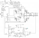
I've looked at them and from what I can tell the differences are the mosfter polarity and the
direct command of the mosfets from the totempole, with a ground common to the PWM integrated circuit.
The reversed polarity of the mosfets works in my case but I can't use a common ground, that's why
I went with a GDT command.
To me they look mostly identical, please correct me if I'm wrong.
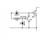
No.
The required waveform is fundamentally different.
This is the inverter waveform (top), and drain waveform at the rectifier, with gate drive disconnected.
Both rectifier transistors must be turned on during dead time (shown here at +12V).
Tim
The required waveform is fundamentally different.
This is the inverter waveform (top), and drain waveform at the rectifier, with gate drive disconnected.
An externally hosted image should be here but it was not working when we last tested it.
Both rectifier transistors must be turned on during dead time (shown here at +12V).
Tim
I suggest you the LTC3722. It's expensive but it gives much more design flexibility. It can be cooperate with a second stage controller to make various modifications. The problem is that you will have to deal with full bridge rectification. Download and the software. It will help you.
- Status
- This old topic is closed. If you want to reopen this topic, contact a moderator using the "Report Post" button.
- Home
- Amplifiers
- Power Supplies
- Synchronous Rectification