hello!
just completed a 5kW powersupply for our high power product, altough my company decided that our next product must be cheaper! currently my company has focused on high performance, and not low cost, and I'm not very experienced in low cost segment.
so to make an isolated, regulated, universial mains supply with PFC, +/- 100v output and about 800w continously.
the cheapest possible way must be making a single stage with PFC and isolation in one converter. and as I see it, there is only 2 topologies feasable:
- flyback, suffers from high peak currents, high voltage stress, large input filter.
- isolated boost (current fed boost-push pull). snubbing? is this even possible? suffers high voltage stress, input current rush needs to be handled.
I'm kind off liking the idea with the isolated boost, since it's so simple in theory. thinking of having to add the buck transistor but only using it during startup, to relieave the design of the usual startup resistor and releay. the buck transistor might be a simple P-FET driven at low speed (20kHz) and could also be used as on/off switch. up and running the reflected output voltage is about 400v. using a simple Atmel 8bit processor for the Avg.mode current control. Im thinking to not use a flyback winding on the inductor, the stresses on the transistors are great enough as it is. 1200v igbts will be used to handle the basic 800v stress +spikes. all the control and regulation is the easy part.
for cost, I think that the input inductor added in the isolated boost is proberly matched by the cost of the DM coil needed as input filter to the flyback. the dual transistor is no problem since the current stress is less.
during simulations, I found that the push pull is actually easier to snub than the full bridge variant, mainly since during cross conduction the leakage in the primary windings actually carries half the current already, which is not the case for the full bridge. meaning that only half the current adds to resonances.
however, even when setting the coupling to 0.998 (leakage of 1uH) in SPICE the amount of dissapation in the snubbers are still like 50W, and it's abit too much to use in an enclosed box.
is there any other cheap topologies possible to use? is the isolated boost really feasable for this kind of design? is there any way of clamping this design without involving floating drivers and such?
I realize that the best design is proberly a boost PFC with a LLC resonant halfbridge, but my guess is that it will be too expencive. it would have 3 magnetic component, together with 3 switches, and some king of inrush limiter.
//Slobban
my precious work is owned by my company, I could never send pictures on this out, for many reasons.
however, the supply is pretty simple. the PFC is a buck+boost type (dual ramp control, avg current mode, hard switching), delivering a maximum of 5kW to a cap bank (400v 10mF). the cap bank stores the peak power. it is allowed to be discharged to 50% of the voltage during the bursts (thus utilizing 75% of the energy stored).
next is an isolated phase shifted full bridge, generating the +/-200v maximum 300A pk. it can delivier 60kW pk. there are no real energy storage after the DC/DC converter so it handles the audio program up to about 2kHz (then the LC filter takes over and the music peaks are averaged), meaning that to be able to produce a 20Hz sine wave of 30kW the peak power will be 60kW.
but basically it's no magical supply, it's just textbook examples of designing DC/DC converters.
the PFC topology is basically ripped off the web (buck and boost using the same coil), but we needed to make our own regulator, since we didnt find any ic to control this type of PFC.
the DC/DC topology is widely known on the web. sadly it could not be afforded to utilize the resonance during turn on, since added leakage in the transformers would yield too much snubbing on the secondary rectifiers (yea I know, it could have been a discrete inductor with clamp diodes but it did not fit), altough we benefit from the topology very much during idle (discontinous operation). the supply only consumes 10W in idle which is extremly good for this kind of high power supply.
the board measures 425 x 185 mm (height ~70mm) cooled by 3 60mm fans (yes, it gets pretty hot when driven to the maximum).
//Slobban
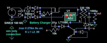
I was just working on something that reminds me of your problem. Mine was converting a 60hz wall wart to a float battery charger. But the problem was absorbing the spikes from the leakage inductance flyback in the power transformer. You might be able to do something vaguely similar even though your frequency is much higher, requiring much more complexity. The spikes are transfered to the output load instead of being dissipated. Probably would need a gate protection zener on the MOSFET gate.
Attachments
Last edited:
aah, ok... now I see... it took me some time to realize what the circuit did... you burn up the spike in the fet. it would have been simpler to use an RCD clamp. the amount of energy would be the same. but a resistor have a far better chance of surviving the energy over the mosfet.
thanks for the suggestion though!
there is an intresting connection between the voltages in a flyback that is puzling my mind. if a capacitor is connected over the flyback transformer, through a diode, and is charged to Vin+spike, when the voltage over the switch is Vin*2. when the switch is closed, you would have the same voltage over the transformer. there should be some way of arranging diodes around this cap, to utilize this connection in voltage potentials to discharge the cap back to Vin when the switch closes. I have been thinking of this for some time, but still I cannot find a good way to make this happen.
//Slobban
When I noticed that my idea wasn't really helping yesterday, I was thinking about the idea of a diode discharging the cap, too. It seems a separate switch would have to be included to do it.  I seem to recall that in theory, an inductor connected between the cap and Vin can discharge the cap, though.
I seem to recall that in theory, an inductor connected between the cap and Vin can discharge the cap, though.
Last edited:
Thanks for expressing your appreciation.
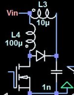
I guess the image I've included below might show something we are trying to think of.
There is another completely different approach, but more complicated, that I have experimented with if this might not be helpful enough. It involves doing the PWM while the transformer is powered by mains AC instead of rectified mains. It eliminates the rectifier bulk capacitor. It involves clamping the transformer after each half cycle. The MOSFETs are configured to operate bidirectionally. I did it using a 60 cycle transformer because I love the ease of slow speed. Maybe it can be done by chopping the AC at a much higher frequency than 60hz as well.
Attachments
Last edited:
- Status
- This old topic is closed. If you want to reopen this topic, contact a moderator using the "Report Post" button.
- Home
- Amplifiers
- Power Supplies
- Isolated PFC Topology choice, 800W.