On output I have only 13V of vdc with load
and (36!) with no load, so there is a huge voltage drop.
Hi, are you saying that you have 13V DC on the output when a load is connected and 36V DC when no load is connected ?
Voltages on diodes are the same as supply (36vdc)
On fets are 12v
Same as output
I will test more but my main question: can this class A PSU work in a single-rail mode:
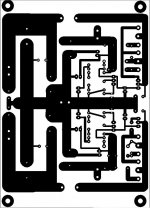
ie can I use only upper part of circuit? If it is so, so I have to debug it. Can be some problem on PCB or some faulty component.
If I feed it from unipolar bridge DC rectifier?
On fets are 12v
Same as output
I will test more but my main question: can this class A PSU work in a single-rail mode:
ie can I use only upper part of circuit? If it is so, so I have to debug it. Can be some problem on PCB or some faulty component.
If I feed it from unipolar bridge DC rectifier?
Ok, my question is answered It was a bad 640 (strange, but it happens)
It can. Feeding from a ready made rectifier (+ to plus rail, - to ground) I can adjust voltage from 36 to 26,2vdc.
It's not a problem for me, since I use it for a mic pre. And extra 2v of headroom just make it beefy. So device with the same components values can regulate within 10v,as it was stated. Haven't noticed any heating problems so far, but ime will tell
And yes. Sound is much "tighter", comparing to LM*** -based PSU
Help, please!
Pls anyone help!!!! It worked 1 day, suddenly R22 gave a smoke.
Also BC640. Replaced, the same story. Under load it gives like a half of supply voltage.
Voltages on 1u similar.
Trimmer don't help much. All problem is around BC640. I replaced few and all give a different result
Only one of 3 worked properly for a while before death.
Under normal working conditions collector of BC640 should give a half of output voltage.
i. e. when it was working normally I had about 12v on it and 25 on output, regarless of load.
As soon as I have a load it shows all weird things
Why the same place all the time? Anyone who is more experienced, tell me where to olook.
I am using MJE29/3050 since I can't get BD241/2 They are not direct replacement, but should work.
Can it be a reason.
Instead BC556 I am using 557, and BC549c instead of 50
help
hello sir Mile
May I use this preamp with your h900amp
as i have completed one but not getting
suitable preamp with decent gain
please help
Im waiting
Mr Mile do you have PCB for these preamplifiers?
hello sir Mile
May I use this preamp with your h900amp
as i have completed one but not getting
suitable preamp with decent gain
please help
Im waiting
hello sir Mile
May I use this preamp with your h900amp
as i have completed one but not getting
suitable preamp with decent gain
please help
Im waiting
Use ML3 preamp from thread: http://www.diyaudio.com/forums/analog-line-level/167363-mic-line-eq-preamps-50.html
Member
Joined 2006
Just noticed this thread...
So this regulator design dates back a decade earlier...")
http://www.diyaudio.com/forums/soli...rly-index-1924-2009-wanted-3.html#post4256021
So this regulator design dates back a decade earlier...
http://www.diyaudio.com/forums/soli...rly-index-1924-2009-wanted-3.html#post4256021
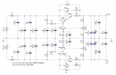
VR 1k must be replaced with 4k7 for BF245A, and regulation output voltage will be from +/12V to +/-24V.
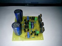
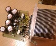
I just completed building the A Class supply.
Using a 12.6V-0-12.6V transformer and 5K ohm trimmers, I can't get the output voltage below +-17.92VDC.
The trimmers have little effect on the output voltages.
Can someone tell me what I need to do in order to get +-12-15VDC?
Thanks.
I don't see any schematics for the PSU-5 would you be able to post any details of PSU-5I see many similarities between PSU-10 and PSU-5,the differences are in voltage of zener-diodes,and parallel connections of the output transistors,also in input and output voltage. I don´t need that high output voltage as it in PSU-10,so PSU-5 is something that I would really like to built for myself ( I need adjustable power supply,to test all kind of amplifiers),but it hasn´t got enough power for my needs due to transistor´s low power limit. Could I add a pair of output transistors to PSU-5 (as it is in PSU-10) without other changes being made,in order to get higher current and power capabilities?
Sent from my SM-G920I using Tapatalk
You can find schematic in thread: http://www.diyaudio.com/forums/solid-state/173462-studio-reference-amplifier.htmlI don't see any schematics for the PSU-5 would you be able to post any details of PSU-5
Sent from my SM-G920I using Tapatalk
Regards
Hello mr. Mile and everbody
I will build class A amplifier.
i need power supply schematic for class a amp. min 1.5a max 3a quiescent current , symmetric 24v.
anyone help me?
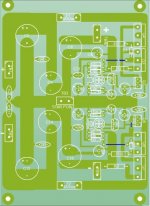
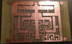
Regulated PSU for class A amp.
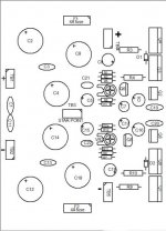
Attachments
Thanks for that. Really appreciate it.You can find schematic in thread: http://www.diyaudio.com/forums/solid-state/173462-studio-reference-amplifier.html
Regards
Can I use this to test a class A-B Amplifier?
Sent from my SM-G920I using Tapatalk
- Home
- Amplifiers
- Power Supplies
- A-class Preamp PSU