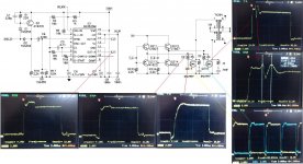
Looks like a commercial design from the way the circuit is drawn.
Why is the "spike" a problem ? Is the unit faulty in some way.
You have to be very careful in just what you call "ground" too, moving the connection to avoid it being influenced by circuit resistances etc as the very high currents have a real effect on measurements..
Why is the "spike" a problem ? Is the unit faulty in some way.
You have to be very careful in just what you call "ground" too, moving the connection to avoid it being influenced by circuit resistances etc as the very high currents have a real effect on measurements..
Thank you for the reply. The spike increases the output voltage, causing problems. Can this spike be a ringing of the ferrite ?
Could the ferrite itself cause the spike ? Or is it the way the coil is wound ?
ferrite material N87 R 50.0 x 30.0 x 20.0 http://www.epcos.com/inf/80/db/fer_07/r_50.pdf
Could the ferrite itself cause the spike ? Or is it the way the coil is wound ?
ferrite material N87 R 50.0 x 30.0 x 20.0 http://www.epcos.com/inf/80/db/fer_07/r_50.pdf
Please help me, this problem is getting irritating. I'not able to drive irfp2907pbf.
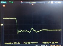
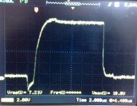
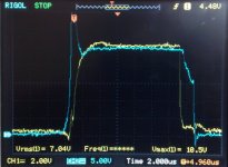
The spike is the main issue because it causes an increase in voltage after the rectifying bridge and I don't want this.
I've tried gate resistors with values between 2 and 100 ohms + a diode for closing, I've even tried a PNP tranzistor for forced closing and still no help.
I've even modified the number of windings on the ferrite and still no result.
The mosfet opening / closing circuit seems to be ok but I get a ringing at 2 different frequencies. I can tame the 4Mhz ringing with a snubber but for the life of me I can't tame the 1.1Mhz ringing.
Please help, i'm on the edge of giving up with the project.
wave form on primary
Attachments
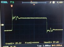
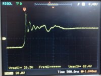
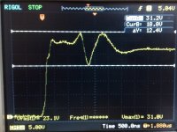
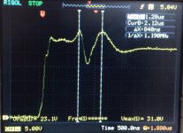
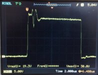
What's the deal with the first and third waveform shots you last posted? Presumably those are both sides of the push-pull? The last one looks passable. If you have the same circuit and are getting different results, then you don't have the same circuit. The layout must be an issue.
(well I meant the post before the last)
(well I meant the post before the last)
Last edited:
- Status
- This old topic is closed. If you want to reopen this topic, contact a moderator using the "Report Post" button.
- Home
- Amplifiers
- Power Supplies
- spike problem !