Hello everyone!
As some of you know, I am working on a table right now. Not a lot is done at the moment, but it's slowly getting there.
Anyway, I selected a motor, and need a power supply for it. I want to switch between 33.33 and 45 'electronically' (read: with a switch), and with the motor I have selected, should be able to do easily.
Easily, with the right power supply!
It is a Coreless DC Motor (9904 120 16206) 24V nominal.
I will be running a 50:1 drive ratio (.250:12.500) so I have worked out the following:
Nominal motor speed (24V) is 2850 RPM
For 33.33 RPM I need a motor speed of 1666.66
For 45 RPM I need a motor speed of 2250
Above RPMs based on nominal RPM, and actual load will govern where to set the voltage of course...
So I'm thinking a variable voltage power supply with good stability and a simple switch with resistors/trim pot so I can 'flip a switch' to change speeds: OFF-33.3-45 which would select the resistance path to limit voltage to the motor.
So the root question is: where do I get a highly accurate DC power source that I can implement my diabolical plan with? I have a power supply now; can I use that with resistors/trim pot on the output to get me where I want to be? Will that be stable over time as (electric) components heat up? I know the oil will heat and start flowing a bit easier (although the oil I selected should be stable at room temperature and well above)
Either a simple build, or pre-made from a vendor, (or another member). I don't have a lot of cash, so it has to be cheap, or you might need something in return?
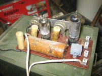
Maybe an OLD tube amp to goof around with?
As some of you know, I am working on a table right now. Not a lot is done at the moment, but it's slowly getting there.
Anyway, I selected a motor, and need a power supply for it. I want to switch between 33.33 and 45 'electronically' (read: with a switch), and with the motor I have selected, should be able to do easily.
Easily, with the right power supply!
It is a Coreless DC Motor (9904 120 16206) 24V nominal.
I will be running a 50:1 drive ratio (.250:12.500) so I have worked out the following:
Nominal motor speed (24V) is 2850 RPM
For 33.33 RPM I need a motor speed of 1666.66
For 45 RPM I need a motor speed of 2250
Above RPMs based on nominal RPM, and actual load will govern where to set the voltage of course...
So I'm thinking a variable voltage power supply with good stability and a simple switch with resistors/trim pot so I can 'flip a switch' to change speeds: OFF-33.3-45 which would select the resistance path to limit voltage to the motor.
So the root question is: where do I get a highly accurate DC power source that I can implement my diabolical plan with?
I have a power supply now; can I use that with resistors/trim pot on the output to get me where I want to be? Will that be stable over time as (electric) components heat up? I know the oil will heat and start flowing a bit easier (although the oil I selected should be stable at room temperature and well above)Either a simple build, or pre-made from a vendor, (or another member). I don't have a lot of cash, so it has to be cheap, or you might need something in return?
Maybe an OLD tube amp to goof around with?
Attachments
For best load regulation, you'd want the motor to be driven from a low impedance voltage source. Thus putting resistors or trimpots in the motor's power line isn't a great way to do it.
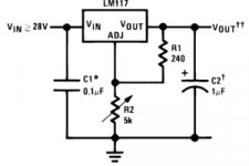
Far better is to drive the motor directly from the output of an adjstable voltage regulator, such as the LM317, and use your speed switch to select either one of two trimpots that adjust the regulators output.
The downloadable datasheet for the LM317 has the design equation to get the right resistance value for any voltage, but the basic layout is shown in the attached pic. Setting R2 to a short circuit will bring the output to 1.2V, i.e., effectively switch off the motor.
Attachments
Thanks for that!
As I mentioned (somewhere) I am ore mechanical than electrical. I know enough to be dangerous!
This looks quite simple to me. Basically, I would replace the pot shown in the picture with a selector switch with the appropriate resistor (and trim pot) to get the speed just right for each selection, right?
And, for off, I'd just cut input power (28V in) rather than keep the chip hot, or is the chip most stable if kept hot?
Finally, would there be any benefit to larger capacitors? Either on the 28V in or within the circuit itself to help 'smooth' the power delivery?
This looks quite simple to me. Basically, I would replace the pot shown in the picture with a selector switch with the appropriate resistor (and trim pot) to get the speed just right for each selection, right?
Exactly so.
And, for off, I'd just cut input power (28V in) rather than keep the chip hot, or is the chip most stable if kept hot?
I have seen several commercial products that power off just by turning the regulators down to 1V, and work like that quite happily for decades.
But either method works - up to you.
Finally, would there be any benefit to larger capacitors? Either on the 28V in or within the circuit itself to help 'smooth' the power delivery?
Reglators don't always like seeing a huge capacitor on their outputs. A capacitor directly at the motor may be benefical - probaly something around 47uF in parallel with 0.05uF. But that does depend on the motor characteristics itself.
The size of capacitor on the unregulated side of the regulator - that depends on your primary DC source. If it's just a basic transformer and rectifier, a big capacitor is good (say 1000uF to 2200uF), but if it is a good quality lab or test bench supply for instance, a capacotor here (other than the one shown in the 317 application note) is rather pointless.
The 317 will need a heatsink, and it must be insulated from the heatsink with a TO-220 mica washer & plastic bush, since the 317's mounting tab is electrically connected to the centre pin.
I have seen several commercial products that power off just by turning the regulators down to 1V, and work like that quite happily for decades.
But either method works - up to you.
Sounds good. I guess a 'master power' at the power cord and then a 'standby' position on the selector switch, which drops the chip to 1v as you say seems reasonable. Only cut the 'main' if going away, or if a storm is brewing...
Reglators don't always like seeing a huge capacitor on their outputs. A capacitor directly at the motor may be benefical - probaly something around 47uF in parallel with 0.05uF. But that does depend on the motor characteristics itself.
Sounds good.
The size of capacitor on the unregulated side of the regulator - that depends on your primary DC source. If it's just a basic transformer and rectifier, a big capacitor is good (say 1000uF to 2200uF), but if it is a good quality lab or test bench supply for instance, a capacotor here (other than the one shown in the 317 application note) is rather pointless.
I will use what I have to supply it; I don't have a 'lab' power supply. A couple large caps is not terribly expensive. I don't need the best money can buy for that task... Would I put one across the + and - rails? (I assume so, but just clarifying)
The 317 will need a heatsink, and it must be insulated from the heatsink with a TO-220 mica washer & plastic bush, since the 317's mounting tab is electrically connected to the centre pin.
This is interesting. If the heat sink I attach is not in contact with any other metal parts is that OK? I assume so... (again clarifying)
By the way, thanks for taking the time to hold my hand through this! I know it is not difficult; however I do not have the background you and others here have, and I truly appreciate the assistance!

I will use what I have to supply it; I don't have a 'lab' power supply. A couple large caps is not terribly expensive. I don't need the best money can buy for that task... Would I put one across the + and - rails? (I assume so, but just clarifying)
Yes, directly across the + & - comming out of the power supply. Pay attention to the voltage rating of the cap (must exceed the power supply voltage, not match it) and the polarity (+ & -). Getting either of those wrong will case the cap to burst or occasionally explode.
This is interesting. If the heat sink I attach is not in contact with any other metal parts is that OK?
If the heatsink is isolated, all will be well with no insulating washer.
BUT I always use washers anyway since a large slab of heatsink is SO easy to accidentally short to ground with tools when working on the circuitry.
You may want to add an extra variable resistor of small value (*) in series with the speed adjust trimpots, on the 'outside' of the TT, where you can get at it easily, as a pitch control.
Speed control of the motor only by constant voltage is not extremely stable long term, so you may need to trim it every so often with a strobe disc. This is very easy if the control is available extrenally.
(*) by small value I mean relative to the calculated value of the trimpot - say 10% of the trimpot resistance.
Last edited:
You may want to add an extra variable resistor of small value (*) in series with the speed adjust trimpots, on the 'outside' of the TT, where you can get at it easily, as a pitch control.
Speed control of the motor only by constant voltage is not extremely stable long term, so you may need to trim it every so often with a strobe disc. This is very easy if the control is available extrenally.
(*) by small value I mean relative to the calculated value of the trimpot - say 10% of the trimpot resistance.
I did not understand this at first, but after reading it a few times I get it.
I was hoping to have the trim pots in the power supply 'accessible' through holes in the case, so it can be trimmed directly there.
However, A better idea I came up with is to use 10-turn pots as you say, with them mounted with the shafts coming out the front of my power supply. This way it can be 'trimmed' as needed with no special tools (other than a strobe) and labeled so anyone could tweak it with no particular knowledge of the circuit.
Cool!
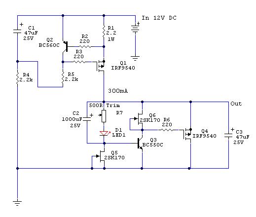
Now, what was this last schematic posted???
Clicked the link and think I have it...
Basically this goes on the output of the 'basic' voltage regulator posted earlier, right?
Make a question to Salas for the output voltage tha needs your motor.
In addition with two trimpots R7 and a switch you can have the 33 and 45rpm.
Yes a basic circuit with lm317 regulator is the power supply!
OK. It gets a bit more complicated, but I think I can still handle it.
Any chance someone could put together a 'complete' schematic of the two circuits in one new drawing?
Then I can make up a BOM and order some parts.
Last thing (hopefully): Is there any value is using a particular transformer type (standard, toroidal, R-core) over another?
Entire power supply will be remotely mounted; however control switch will be on the plinth for ease of use... Any issues with running the motor feeds in the same cable as the control wires? Any need for shielding on this cable? (as DC I would think not, but just checking).
Thanks again! This is going to be pretty nice when done I think!
An alternative that theoretically should give better speed regulation than a constant voltage source, is a constant current regulator. The motor speed should then be largely independant of load fluctuations (the whys require an explanation of DC motor operational theory which I'll spare everyone the ugly details of it on here, but I put some of it as pertaining to my Technics motor on my web page: <<sp10the.pdf>> )
The LM317 can also be configured as a current regulator, but you'd need to measure the current consumption of your motor at both speeds before computing circuit components.
The LM317 can also be configured as a current regulator, but you'd need to measure the current consumption of your motor at both speeds before computing circuit components.
Last edited:
An alternative that theoretically should give better speed regulation than a constant voltage source, is a constant current regulator. The motor speed should then be largely independant of load fluctuations (the whys require an explanation of DC motor operational theory which I'll spare everyone the ugly details of it
I disagree. Torque (not speed) is proportional to the current . (Winding torque = tw(t) = kt ia (t))
" The back or counter EMF acts as a control for the amount of current needed for each mechanical load. When the mechanical load is increased, the first effect is a reduction in speed. But a reduction in speed also causes a reduction in back EMF, thus making available an increased voltage for current flow in the armature. Therefore, the current increases which in turn increases the torque. Because of this action, a very slight decrease in speed is sufficient to meet the increased torque demand. Also, the input power is regulated to the amount required for supplying the motor losses and output."
Taken from: Reliance - Basic Motor Theory
So more load means more current implying constant current means a speed change with a load change.
which also shows how different windings cause different speed regulation.
Jim, my only suggestion (if you havent thought of it already) is to adjust the speed while playing a record, ie with the motor loaded.
Last edited:
I disagree. Torque (not speed) is proportional to the current .
You are absolutely right! Where was my mind!?
Ignore me when I write rubbish.
I must not write posts late at night when half alseep...
I must not write posts late at night when half alseep...
I must not write posts late at night when half alseep...
Hello everyone!
So I'm thinking a variable voltage power supply with good stability and a simple switch with resistors/trim pot so I can 'flip a switch' to change speeds: OFF-33.3-45 which would select the resistance path to limit voltage to the motor.
Sounds like you want a PWM controller, or Pulse width modulation controller. This device creates a square waveform with an adjustable duty cycle that can adjust the On time of the waveform. A device with 100% duty cycle will deliver DC power, and a duty cycle of 0% is powered off. a 50% duty cycle is half on, half off.
A DC motor powered with a low duty cycle will spin slowly, but deliver near the same torque if it was running with a 100% duty cycle. Using an adjustable voltage supply is a bad idea as it will reduce the torque.
In addition it would pretty easily to design a PWM curcuit using a 555 Timer with two speed using simple dpdt toggle switch using two sets of timing resistors (to deliver the speeds you need). There are tons of webpages with circuits using 555 PWM circuits as variable speed motor controllers.
In the simple LM555 PWM motor controller circuit I found on the web you just need to use two pots set tuned to the speeds you need, and the dpdt switch that connects the pot wiper to 1K resistor. Connect the the other pot connections in parallel and to the connections shown in the circuit.
An externally hosted image should be here but it was not working when we last tested it.
The only problem is that I think most 555 are limited to 18V or 20V. You make need to reduce the Vcc voltage (which can be done using a pair of resistors in series with a center tap that connects the 555 Vcc to reduce the voltage. You can also use a linear regulator ie LM317, LM7812, but it just costs more than a pair of resistors. The 555 will have a very low and very fixed current demand. for a Input voltage of 24V a 1/8 or 1/4 watt 220 ohm resistor connect to 24V connected to a 470 ohm resistor connected to ground should supply about 16VDC to the 555.
if you need something that delivers real accurate rpms that make small dynamic adjustments to the PWM output to maintain a steady speed, Google for PWM motor controllers using a PLL (Phased lock Loop).
I get the impression that the Op wanted something SIMPLE, with no need for much electronic design.
A straight linear reglator like the LM317 is very much what most of the low to mid-price belt drives of the 1980s used, and also used in most cassette decks.
It's a start. IF you find it is too wow-prone, then complicate things, but it may be all you need.
A straight linear reglator like the LM317 is very much what most of the low to mid-price belt drives of the 1980s used, and also used in most cassette decks.
It's a start. IF you find it is too wow-prone, then complicate things, but it may be all you need.
- Status
- This old topic is closed. If you want to reopen this topic, contact a moderator using the "Report Post" button.
- Home
- Amplifiers
- Power Supplies
- Turntable Motor Power supply