I am wiring up my dual bridge power supply. One bridge for + rail and another bridge for the - rail.
Just like the first watt power supplies and chipamp power supplies.
Example, F1 manual, go to page 9. Link.
Example, chipamp.com PS, go to page 4 - Link.
Or just look at this (from chipamp.com).
Note that none of these schematics have the little dots indicating secondary polarity.
Question: Does it matter that the top and bottom secondaries are in-phase or out of phase with each other? If so which is the way to do it (assume in phase but I could be wrong).
Just like the first watt power supplies and chipamp power supplies.
Example, F1 manual, go to page 9. Link.
Example, chipamp.com PS, go to page 4 - Link.
Or just look at this (from chipamp.com).
An externally hosted image should be here but it was not working when we last tested it.
Note that none of these schematics have the little dots indicating secondary polarity.
Question: Does it matter that the top and bottom secondaries are in-phase or out of phase with each other? If so which is the way to do it (assume in phase but I could be wrong).
I am wiring up my dual bridge power supply. One bridge for + rail and another bridge for the - rail.
Just like the first watt power supplies and chipamp power supplies.
Example, F1 manual, go to page 9. Link.
Example, chipamp.com PS, go to page 4 - Link.
Or just look at this (from chipamp.com).
An externally hosted image should be here but it was not working when we last tested it.
Note that none of these schematics have the little dots indicating secondary polarity.
Question: Does it matter that the top and bottom secondaries are in-phase or out of phase with each other? If so which is the way to do it (assume in phase but I could be wrong).
I can't imagine how it could matter. It just defines which diodes are conducting on a particular half cycle. My question is how is this better than wiring the secondaries in series and using 1 bridge instead of 2 ? One minor downside is you lose .7 Volts because of the extra diodes in the path in this scheme.
G²
Apart from the increased voltage drop from using 2 separate bridge rectifiers, the only real advantage is reducing the thermal stress on the bridge rectifiers when used in high power amplifiers.🙂
Well, I asked myself just the same question when I build my chipamp, and so I tried out both versions, in phase and out of phase. And the difference was: none! Neither in sound quality nor regarding the general function of the amp. So I would guess it really doesn't matter.
Regards!
martin
Regards!
martin
I can't imagine how it could matter. It just defines which diodes are conducting on a particular half cycle. My question is how is this better than wiring the secondaries in series and using 1 bridge instead of 2 ? One minor downside is you lose .7 Volts because of the extra diodes in the path in this scheme.
G²
This Article on tnt-audio.com says two bridges are good. I just did it that way cause I had a 2 bridge PCB, not for any real techie reason.
Note that even here the phase of each secondary is not mentioned. Leaving it to the reader to be confused!
Lastly, Figure 4 illustrates a serious power supply. For a start, we see that each half of the supply has its own full wave bridge rectifier. This allows for significantly improved rectification, as well as offering the designer greatly increased power handling capabilities, since two rectifiers now share the work load of one. This approach is quite common in American High End units, and has during the last several years begun to trickle downwards, into higher middle class units. A welcome change indeed.
But the real reason why this is done is twofold. First, this allows for much better channel separation, since each supply line is independent, and is therefore much less likely to transmit signal from one channel to the other. The other reason is essentially the same, but with regard to ground planes - this method produces more ground planes, but avoids mixing them, thus once again minimizing possibilities of crosstalk and improving our signal to noise ratios. For this to be so, one also needs dedicated transformer secondary windings, for a stereo amp a total of four, rather than the classic two. Obviously, while good and with many advantages, this is a considerably more expensive design.
Last edited:
Hi
The first diagrams posted are correct but not this last one.
The advantage of dual rectifiers is clean and quiet GROUNDING full stop. This is best configured by using a star ground. This star is at the junction of both returns at the lowest ripple point ie at the cap outputs. Not as shown in this last figure> The draw back is you have 2 diode drops instead of one. Double bridge rectifiers are best ONLY If you have dual secondaries.
Nothing is gained by using double bridges for a common center tapped XFMR, then using one bridge carefully implemented is best.
Hi
The first diagrams posted are correct but not this last one.
The advantage of dual rectifiers is clean and quiet GROUNDING full stop. This is best configured by using a star ground. This star is at the junction of both returns at the lowest ripple point ie at the cap outputs. Not as shown in this last figure> The draw back is you have 2 diode drops instead of one. Double bridge rectifiers are best ONLY If you have dual secondaries.
Nothing is gained by using double bridges for a common center tapped XFMR, then using one bridge carefully implemented is best.
OK, that is what I thought too. But what about the relative phase(s) of the secondaries? Does it matter if they are in phase or out of phase or not?
Sorry I thought that had been answered, No phase doesnt matter for dual secondary dual bridge.
The diodes steer it in the right direction before they are tied together
The diodes steer it in the right direction before they are tied together
Last edited:
What silliness is this? 

1. Rectification isn't improved, it's impaired. The voltage drop is *doubled*.
2. The "duh" answer: increase power handling by using a properly rated bridge. They make single unit FWB's good for well over 100A, or you can buy individual diodes (stud, module or puck style), which are easier to cool and are available into the kiloamp range.
3. This is the real reason -- "because they did it". Audiophoolery, as a cultural phenomenon, cares not for rational thought. (So why even bother wasting my time, right?)
4. WTF? The channels are on the same +/- rails! They aren't on positive only and negative only!
The proper solution is to connect the secondaries in series (the phase is obvious to check and nonfatal if wrong -- if the end-to-end voltage is near 0V, it's backwards) and use one FWB. The CT between windings comes straight out as GND.
Tim
Lastly, Figure 4 illustrates a serious power supply. For a start, we see that each half of the supply has its own full wave bridge rectifier. This allows for significantly improved rectification, as well as offering the designer greatly increased power handling capabilities, since two rectifiers now share the work load of one.
1. Rectification isn't improved, it's impaired. The voltage drop is *doubled*.
2. The "duh" answer: increase power handling by using a properly rated bridge. They make single unit FWB's good for well over 100A, or you can buy individual diodes (stud, module or puck style), which are easier to cool and are available into the kiloamp range.
This approach is quite common in American High End units, and has during the last several years begun to trickle downwards, into higher middle class units. A welcome change indeed.
3. This is the real reason -- "because they did it". Audiophoolery, as a cultural phenomenon, cares not for rational thought. (So why even bother wasting my time, right?)
But the real reason why this is done is twofold. First, this allows for much better channel separation, since each supply line is independent, and is therefore much less likely to transmit signal from one channel to the other.
4. WTF? The channels are on the same +/- rails! They aren't on positive only and negative only!
The proper solution is to connect the secondaries in series (the phase is obvious to check and nonfatal if wrong -- if the end-to-end voltage is near 0V, it's backwards) and use one FWB. The CT between windings comes straight out as GND.
Tim
Sch3mat1c is right: it is indeed a load of nonsense.
In addition, the dual bridge scheme creates more paths for RF modulation by the diodes, and more sources of reverse recovery noise.
It also impairs the grounding, because the transformers windings have no direct galvanic connection to the ground, and cannot act as a partial shield against mains-borne interferences.
Finally, in the zero-crossing region of the mains waveform, the windings are left completely floating, high-impedance.
the phasing of the dual secondaries is irrelevant when attaching the dual bridge rectifiers.
The voltage drop through the dual rectifier is double that of the single rectifier.
A dual rectifier arrangement will dissipate double the heat that a single rectifier will dissipate. Each rectifier has to get rid of the same heat. Nothing is gained current wise nor heatwise by going to double rectifiers.
A single rectifier attached to a centre tapped transformer and a double rectifier attached to a dual secondary transformer will perform exactly the same except for the extra volts loss of ~0.7Vdc per supply rail. This is based on my measurement capabilities and listening abilities when powering a single channel.
When powering two channels, I have found that 4bridge rectifiers forming two separate dual polarity supplies offers the advantage of separate Audio Ground for the two channels in a pseudo dual mono chassis. This sometimes results in more tolerance to oddly wired source components that can produce hum from the speaker. This slightly more tolerant arrangement is never as good as a pair of true monoblocks.
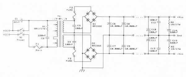
Not taking sides in the 1-or-2-rectifiers-is-better debate, but is the lower bridge correctly drawn in the diagram in the first post ?
The 1st diagram just the reverse the diode bridge ( or labels) giving the opposite polarity for the bottom section. The wiring is correct, in that they need to be wired as separate section.
The last figure ( polarity correct) wrongly joins the sections at the bridges and places the chassis connection at the noisiest place. The common connections need to be joined lastly at the output caps otherwise you'll lose any advantage of the dual bridges.
dual vs single is best explained here
The last figure ( polarity correct) wrongly joins the sections at the bridges and places the chassis connection at the noisiest place. The common connections need to be joined lastly at the output caps otherwise you'll lose any advantage of the dual bridges.
dual vs single is best explained here
Sch3mat1c is right: it is indeed a load of nonsense.
In addition, the dual bridge scheme creates more paths for RF modulation by the diodes, and more sources of reverse recovery noise.
It also impairs the grounding, because the transformers windings have no direct galvanic connection to the ground, and cannot act as a partial shield against mains-borne interferences.
Finally, in the zero-crossing region of the mains waveform, the windings are left completely floating, high-impedance.
I disagree on the zero crossing issue which would be high impedance regardless since the diodes are all reverse biased because of the filter caps.
G²
Not if you have the center tap grounded.I disagree on the zero crossing issue which would be high impedance regardless since the diodes are all reverse biased because of the filter caps.
G²
Can anyone suggest a decent single package bridge rectifier for a dual bridge psu, or indeed discrete diodes? Seen some posts saying to steer away from packaged bridges. Application is for a couple of slone optimos amps, so 200W + 200W.
Here is an expensive high end one.
IXYS Fast Recovery at digikey
Here is more of a plain-vanilla one
Typical Bridge at Mouser.
This second kind is at apexjr.com cheap.
IXYS Fast Recovery at digikey
Here is more of a plain-vanilla one
Typical Bridge at Mouser.
This second kind is at apexjr.com cheap.
Does the dual bridge have an advantage?
I have seen many amplifiers adopt the dual bridge approach. It clarly has some disadvantages, not the least of which is cost if good fast-recovery rectifiers are used - twice as many. It also suffers the disadvantage of twice the number of junction drops in rectification, resulting in a slight loss of rail voltage. For the same reason, total rectifier power dissipation is doubled. So why are many reputable manufacturers going this way if it carries with it extra cost?
Here are a couple of assertions that have been made for why it may be preferred in spite of its increased cost and rectifier losses.
I'm interested to hear your opinions on the validity of these reasons.
First, the dual bridge approach prevents the circulation of DC in the secondary windings when the load current on the positive and negative rails is not equal. Transformers, especially toroids, don't like DC flowing in their windings, as it can push them toward core saturation, degrade transformer performance, and result in buzzing (this is also a concern for DC in the primaries due to residual DC on the mains).
Secondly, the high peak rectification currents involving the loop consisting of the secondary, rectifiers and reservoir capacitor, those currents are resolved locally without passing through ground.
Thirdly, it has been stated that EMI from the mains to the secondary has less opportunity to get to the circuits on the secondary side because the transformer windings are only "connected" to the secondary circuits during the brief rectifier on times. In the single-bridge rectifier scheme, the transformer is always connected to the circuits on the secondary side via the grounded center tap.
I must admit that it is a little unclear whether having the secondaries "float" when the rectifiers are not conducting is better or worse.
Note that power transformers have very substantial amounts of coupling capacitance from primary to secondary, toroids more than frame transformers. I measured a 500VA toroid to have 1300 pf, while a 500VA frame transformer measured about 600 pF.
Cheers,
Bob
sorry to revive this old thread.
Just to say that i modded my diy power supply for my MOTU 24i/o interface from center tapped to dual rectifiers ( the trafo has dual secondaries) and the lm3*7 regulators get clearly less hot. All the rest remais the same.
I'll take it as an advantage.
RMAA readings on channel one in the MOTU remained the same after the mod.
- Status
- Not open for further replies.
- Home
- Amplifiers
- Power Supplies
- Dual Bridge PS - Does Phase of Secondary Matter?