I've always been interested in power supplies. And often have read that schottky's are still noisier than tube rectifiers. The reason being that the schottky have even more violent reverse recovery spikes. With a tube amp, there are often multiple windings. And the reverse recovery spike "noise" is capacitively coupled to the other winding(s).
This week I saw -ecdesigns- 3-stage stepped rectifier. And subsequently googled it. Not a lot of info or implementations came up.
But I was wondering how this is all that different from just adding a reverse recovery spike filter as for instance the bottlehead folks are fond of doing? I came to think that it perhaps had to do with the fact that the 3 stage stepped rectifier prevents the spikes but can ALSO deliver more current when needed compared to a standard solid state rectifier with RRSF.
I am also curious as how one calculates what value resistors are needed.
And further info on the sense...or non sense of a stepped rectifier would be welcome...
Thanks in advance.
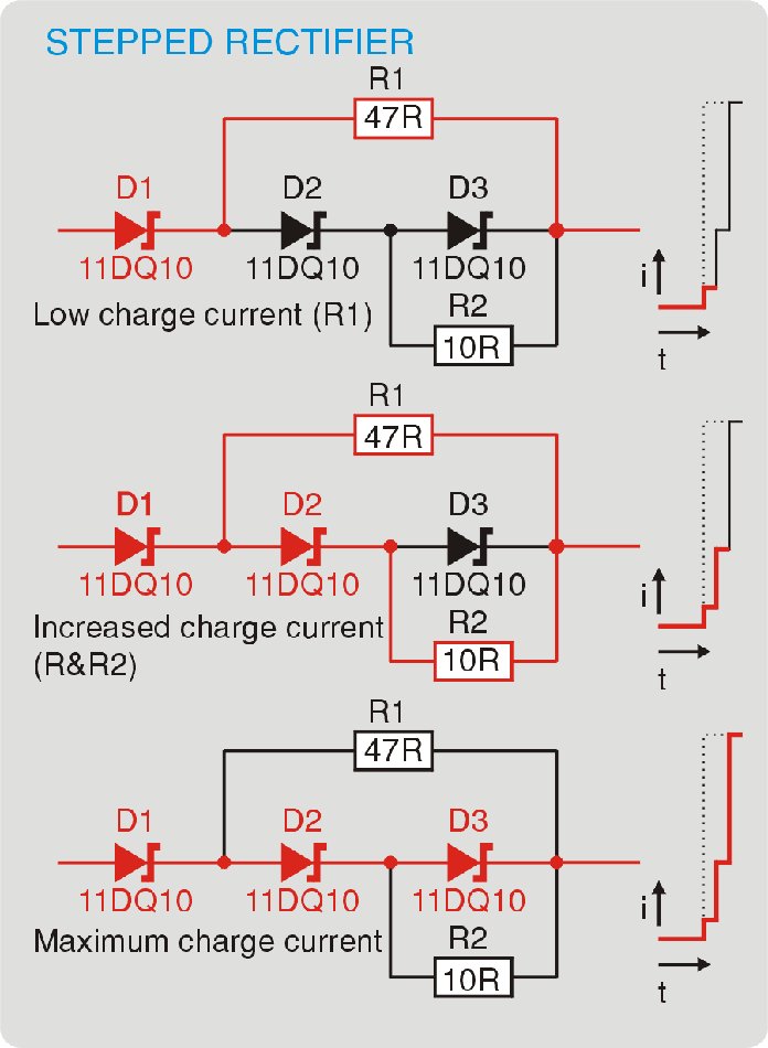
A picture:
(Oh and yes...I know tube rectifiers have their shortcomings...let's not go there please 😉 )
This week I saw -ecdesigns- 3-stage stepped rectifier. And subsequently googled it. Not a lot of info or implementations came up.
But I was wondering how this is all that different from just adding a reverse recovery spike filter as for instance the bottlehead folks are fond of doing? I came to think that it perhaps had to do with the fact that the 3 stage stepped rectifier prevents the spikes but can ALSO deliver more current when needed compared to a standard solid state rectifier with RRSF.
I am also curious as how one calculates what value resistors are needed.
And further info on the sense...or non sense of a stepped rectifier would be welcome...
Thanks in advance.
A picture:
(Oh and yes...I know tube rectifiers have their shortcomings...let's not go there please 😉 )
Last edited:
Yes, ferrite bead or what have you. It's not like 60Hz has big dV/dt or anything. Regular 1N4007s work fine. If it's buzzing, add a snubber (R+C, not just C which is the brute force method). If it's still buzzing, put a few microhenries in series.
FYI, schottkies have "no" reverse recovery, which means an irreversible gulp of charge when turning off the diode. Junction diodes do, because it takes real work to pull the charge out of the junction when turning off, and to push them back in when turning on. If you drew a plot of V vs. Q (Q is charge, the integral of current) for one cycle, you'd see a skewed hysteresis loop, the area being (mostly) energy lost due to recovery, and the skew corresponding to the amount of charge delivered (since it does rectify, after all). A schottky diode has a big charge, because its capacitance is large (a typical 30V, 30A rectifier found in computer supplies has a whopping ~10nF near zero bias -- it would make an excellent AM broadcast band tuning diode!). But that charge is reversible, so the V-Q curve follows the same path back (again, not counting rectified current).
Tim
If you like the tube rectifier thing, check out the rectifiers from Qspeed
(formerly Lovoltech). Some of their stuff is very fast, high voltage and
has a pretty high forward drop. Not really suitable for what I do, but it
looks a lot like a tube rectifier.
😎
(formerly Lovoltech). Some of their stuff is very fast, high voltage and
has a pretty high forward drop. Not really suitable for what I do, but it
looks a lot like a tube rectifier.
😎
Yes, I've had good results from the QSpeed diodes (LQA60A330C, and the 16A version); notably quieter in terms of switch-off behaviour than a regular 35A bridge rectifier block.
For 'small' PSUs I'm just as likely to reach for something like UF4007 - cheap and very effective.
For 'small' PSUs I'm just as likely to reach for something like UF4007 - cheap and very effective.
Last edited:
I've always been interested in power supplies. And often have read that schottky's are still noisier than tube rectifiers. The reason being that the schottky have even more violent reverse recovery spikes. With a tube amp, there are often multiple windings. And the reverse recovery spike "noise" is capacitively coupled to the other winding(s).
This week I saw -ecdesigns- 3-stage stepped rectifier. And subsequently googled it. Not a lot of info or implementations came up.
But I was wondering how this is all that different from just adding a reverse recovery spike filter as for instance the bottlehead folks are fond of doing? I came to think that it perhaps had to do with the fact that the 3 stage stepped rectifier prevents the spikes but can ALSO deliver more current when needed compared to a standard solid state rectifier with RRSF.
I am also curious as how one calculates what value resistors are needed.
And further info on the sense...or non sense of a stepped rectifier would be welcome...
Thanks in advance.
A picture:
(Oh and yes...I know tube rectifiers have their shortcomings...let's not go there please 😉 )
I have implemented the EC design almost on the all stages on my CD player, separated trafo's and psu boards for, TDA 1541, SAA7220, SAA7310, RAM.....
Sounds very good.
You can always give SiC diodes a try (e.g from Infineon or Cree), they are shottkys, have next to no reverse recovery, and are very low noise - I use them in my tube preamp and they are excellet, albeit expensive.
In this stacked shottky, the issue I see is that D1 will have to support the full input voltage, so this approach cannot be used for tube circuits (at least not with silicon-based shottkys, they are limited to 200V or so).
Calculating the resistors is straightforward, I guess, once you determine the output currents at which the two next diodes are supposed to turn on, and you know their forward voltage drop, R2 =VF/I2, and R1=(2xVF)/I1.
But I wonder why this should be good sounding, imagine a power amplifier (class B) drawing a sinusoidal current at higher power, and this rectifier circuit would introduce two more step functions in the output impedance of the power supply... should show up nicely in a spectrum analyser....
I have implemented the EC design almost on the all stages on my CD player, separated trafo's and psu boards for, TDA 1541, SAA7220, SAA7310, RAM.....
Sounds very good.
Can you please post a link to the schematic you've used. I cannot find an example. I don't dare to cobble up one on the info in this thread.
Thank you, arco
- Status
- Not open for further replies.
- Home
- Amplifiers
- Power Supplies
- 3-stage stepped rectifier. Theory?